

9
INSTALLATION PROCEDURES –
Electrical
CHAPTER 5
The CD1500P and CD2000P ozone
generators are equipped with universal
regulated power supplies that accept an
input voltage from 90-250VAC at 47-
63Hz, single phase (1
ø
). ClearWater Tech
has an assortment of IEC cords for various voltage
requirements and outlet configurations, for use around
the world. All possible pre-wiring has been completed
at the factory. Logic schematics have been provided in
the Appendix-Section D.
• All electrical connections should be made by a
licensed, qualified electrician. All local, state and
national codes must be observed.
• Make sure all power is off at the main circuit
breaker before making any electrical connections.
Step 1:
Conforming to all local, state and national electrical codes, ground the ozone generator to a true earth ground.
Use solid copper bonding wire (usually #8 AWG) from the copper-bonding lug located on the bottom of the
ozone generator to the grounding point.
Step 2:
Main Power:
Plug the IEC end of the power cord into the
power entry module located at the bottom of the ozone
generator. The other end can be plugged into any main
power source with input voltage from 90 to 250 VAC at 47
to 63 Hz, single phase.
Step 3:
External Loop (EXT LOOP):
The external loop is a true dry contact interface.
Note: The term ‘dry
contact’ means that this loop does not supply output nor except input voltages. Warning: Supplying
voltage to the external loop will cause damage to the ozone generator and void warranty.
Under normal
operation, the external loop will effectively interrupt the ozone output when the loop has lost continuity; this
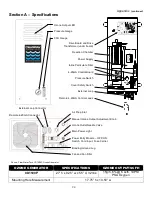
will also illuminate the LED located on the 4-20mA control board inside the ozone generator (see Appendix,
Section A, for location of board) and turn off the “Ozone Output” LED(s) on the front cover.
Note: When the
external loop has lost continuity main power to the ozone generator will remain “ON” giving power to
the cooling fan(s).
When continuity is present through the external loop, ozone output will continue. This
continuity will effectively turn “OFF” the LED of the 4-20mA board and will again illuminate the “Ozone
Output” LED(s).
The external loop, a removable two-position plug with a white 18AWG wire located at the bottom panel of the
ozone generator (see Appendix, Section A), can be interfaced to any control device, i.e., pressure switch,
vacuum switch, flow switch, float switch, ORP controller, PPM controller, or timer. To interface a control
device to the external loop, cut the white 18AWG wire in half. Connect the control device to each leg of the
external loop.
Note: External Loop control devices supplied by ClearWater Tech may come equipped
with a two-position male connector ready to be plugged into the female two-position connector mounted
to the chassis of the ozone generator.
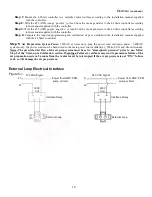
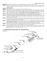
If the control device used supplies an output voltage a single pole
single throw (SPST) normally-open relay may be used to create a dry contact interface (see Figure 5-1,
“External Loop Electrical Interface”).
Note:
Attached to the white 18 AWG external loop is a warning,
“THIS CONNECTION IS A DRY CONTACT ONLY, DO NOT APPLY VOLTAGE”.
Step 4:
Ozone Output Control:
The CD1500P and CD2000P ozone generators are equipped with two options for
controlling the ozone output. The first option is a manual 0-100% ozone output control and the second is a
remote 4-20mA control signal. The manual ozone output control knob and remote 4-20mA control leads
(orange and purple) are located at the bottom of the ozone generator (see Appendix, Section A).
1.
Manual Ozone Output Control:
Turning the control knob counterclockwise will decrease the ozone output down to
0% while turning the knob clockwise will increase the ozone output up to 100%. The ozone output level is indicated
by the “Ozone Output” LED(s) on the front cover of the ozone generator (see Appendix, Section A).
2.
Remote 4-20mA Control:
A 4-20mA control signal to the ozone generator may be used to control the ozone
generator output. The ozone generator will automatically sense the 4-20mA input signal and override the setting of
the manual ozone output control. Based on the 4-20mA signal, ozone output will increase or decrease: 4mA = 0%
ozone output, 20mA = 100% ozone output. The ozone output level is indicated by the “Ozone Output” LED(s) on the
front cover of the ozone generator (see Appendix, Section A).
Note: If the remote 4-20mA signal fails or is
missing, the system will default to the manual ozone output setting. Check and adjust the manual ozone
output control knob to avoid over-ozonation.
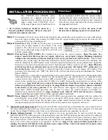
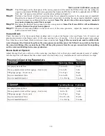
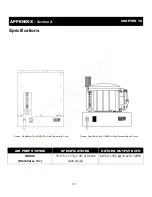
Power Consumption
Input Voltage
90-250VAC 47-63Hz
CD1500P
1.6 - 0.8 amps
CD2000P
2.8 - 1.4 amps


