Sect06_CSMG_b.fm
6-6
04/22/2019
Steam Master Instruction Manual
b. Obtain a 3/16 in. x 6 in. (4 mm x 150 mm)
rod, dowel, pencil, or similar device. This
rod will be inserted through the breather
hole for testing.
POTENTIAL LOSS OF OFF FINGERS!
Fingers caught between belt and pulley may be
cut off. This procedure is performed while the
feedwater pump is operating.
c. With the feedwater pump operating, insert
the rod into the breather hole in the base of
the intake surge chamber/discharge snub-
ber housing until it stops.
d. Verify the rod modulates in an up and
down motion. If the rod fails to do this,
then the intake surge chamber / discharge
snubber requires replacement.
6.6
Semi-annual Service
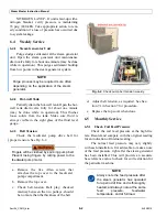
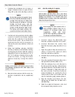
Test feedwater pump relief valve (Fig. 6-5)
operation. Slowly, close the coil feed valve until the
feedwater discharge pressure exceeds the relief
valve’s set pressure, typically 275 psi (1,896 kPa).
Verify relief valve is discharging properly and ver-
ify the drain lines are clear of blockage for proper
draining. See Section 7.2 adjustment and mainte-
nance procedures.
NOTE
Increase maintenance intervals to
three months on older feedwater
relief valves.
Fully open the coil feed valve after feedwater
pump relief valve check is complete.
6.7
Annual Service
NOTE
Perform this annual service semi-
annually if the steam generator is in
use 24 hours a day, 7 days a week
(or similarly continuous operation).
Fig. 6-4.
Feedwater pump relief valve.
Fig. 6-5.
Feedwater pump relief valve.
COIL FEED VALVE
Содержание Steam Master CSMG-15
Страница 1: ...STEAM MASTER SERIES USER MANUAL Cover CSMG 15 30 40 R027880B 20190603 ...
Страница 8: ...vi The controls and features may differ depending on the unit s size and specifications ...
Страница 9: ...vii The controls and features may differ depending on the unit s size and specifications ...
Страница 14: ...Specifications_CSM_a fm xii 11 22 2018 This page intentionally left blank ...
Страница 26: ...Sect02_CSMG_b fm 2 6 04 19 2019 Steam Master Instruction Manual This page intentionally left blank ...
Страница 44: ...Sect05_CSMG_a fm 5 6 11 26 2018 Steam Master Instruction Manual NOTES ...
Страница 56: ...Sect06_CSMG_b fm 6 12 04 22 2019 Steam Master Instruction Manual This page intentionally left blank ...
Страница 66: ...Sect07_CSMG_b fm 7 10 04 26 2019 Steam Master Instruction Manual This page intentionally left blank ...
Страница 68: ...HeatingSect_SM15_a fm A 2 04 30 2019 Fig 01A Main Heating Section SM15 ...
Страница 69: ...04 30 2019 A 3 HeatingSect_SM15_a fm FIG 01A Main Heating Section SM15 ...
Страница 70: ...HeatingSect_SM15_a fm A 4 04 30 2019 Fig 01B Economizer Stack Outlet Kit SM15 ...
Страница 71: ...04 30 2019 A 5 HeatingSect_SM15_a fm FIG 01B Economizer Stack Outlet Kit SM15 ...
Страница 72: ...HeatingSect_SM30_b fm A 6 12 05 2018 Fig 01C Main Heating Section SM30 ...
Страница 73: ...12 05 2018 A 7 HeatingSect_SM30_b fm FIG 01C Main Heating Section SM30 ...
Страница 74: ...HeatingSect_SM30_b fm A 8 12 05 2018 Fig 01D Economizer Coil SM30 ...
Страница 75: ...12 05 2018 A 9 HeatingSect_SM30_b fm FIG 01D Economizer Coil SM30 ...
Страница 76: ...HeatingSect_SM45_b fm A 10 04 30 2019 Fig 01C Main Heating Section SM40 ...
Страница 77: ...04 30 2019 A 11 HeatingSect_SM45_b fm FIG 01C Main Heating Section SM40 ...
Страница 78: ...HeatingSect_SM45_b fm A 12 04 30 2019 Fig 01D Economizer Coil SM40 Sht 1 of 2 ...
Страница 79: ...04 30 2019 A 13 HeatingSect_SM45_b fm FIG 01D Economizer Coil SM40 ...
Страница 80: ...Sep Trap PressMfld_SM153040_b fm A 14 04 30 2019 Fig 02A Steam Discharge and Separator Hookup SM 15 ...
Страница 81: ...04 30 2019 A 15 Sep Trap PressMfld_SM153040_b fm FIG 02A Steam Discharge and Separator Hookup SM 15 ...
Страница 82: ...Sep Trap PressMfld_SM153040_b fm A 16 04 30 2019 Fig 02B Steam Discharge and Separator Hookup SM 30 40 ...
Страница 83: ...04 30 2019 A 17 Sep Trap PressMfld_SM153040_b fm FIG 02B Steam Discharge and Separator Hookup SM 30 40 ...
Страница 86: ...Sep Trap PressMfld_SM153040_b fm A 20 04 30 2019 Fig 02E Pressure Indicating System ...
Страница 87: ...04 30 2019 A 21 Sep Trap PressMfld_SM153040_b fm FIG 02E Pressure Indicating System ...
Страница 90: ...PumpHkup C1 C2_parts_a fm A 24 03 05 2019 Fig 05A Pump Assy C1 ...
Страница 91: ...03 05 2019 A 25 PumpHkup C1 C2_parts_a fm FIG 05A Pump Assy C1 ...
Страница 92: ...03 05 2019 A 26 PumpHkup C1 C2_parts_a fm Fig 05B Pump Assy C2 ...
Страница 93: ...PumpHkup C1 C2_parts_a fm A 27 03 05 2019 FIG 05B Pump Assy C2 ...
Страница 98: ...Blank_Left fm A 32 08 16 2017 This page intentionally left blank ...
Страница 104: ...25 75 bhp Feedwater Skid Option FeedwtrSkid_VHtwl_25 75bhp_a fm B 6 11 26 2018 This page intentionally left blank ...
Страница 106: ...R027906A 2018 10 22 ...
Страница 107: ...NOTES ...
Страница 108: ...Steam Generator Instruction Manual This page intentionally left blank ...
Страница 109: ......


