11/15/2018
4-5
Sect04_CSM_a.fm
Section IV–Operating Instructions
4.7
I
NTERMITTENT
F
ILL
/W
ET
L
AY
-
UP
Intermittent fill maintains a “wet” coil. This
operation is active when the unit is in wet lay-up.
Wet lay-up is used when the unit will be shut down
for only a short period. The INTERMITTENT
FILL WATER PUMP ON message appears on the
left of the screen (Fig. 4-10) while the unit is in wet
lay-up.
The wet lay-up process is initiated by pressing
the AUTO SHUT DOWN icon on the main menu
screen (Fig. 4-1 on page 4-1).
Verify the bypass valve is open. Verify the
header valve, dry shut down valve, and
maintenance drain valve are tightly closed. Make
sure feedwater quality is maintained throughout the
wet lay-up period. Verify there are no leaks
anywhere in the plumbing during wet lay-up.
4.8
D
RY
S
HUT
D
OWN
The unit will develop rust or other forms of
oxidation inside the coil tubing if dry shut down
is executed improperly.
A dry shut down should be performed
by Clayton service personnel or other
personnel who are thoroughly trained in
Clayton steam generators.
A dry shut down maintains a “dry” coil when
a unit will be shut down for a prolonged period—
usually exceeding 14 days.
The dry shut down process is initiated by
pressing the DRY SHUT DOWN icon on the main
menu screen (Fig. 4-1 on page 4-1).
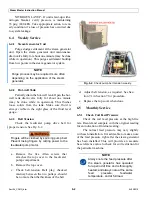
The “dry shutdown in progress” screen (Fig.
4-11) will display and step through the shut down
process.
The operator must be present
throughout this process to perform
required operations as indicated on the
screen (Fig. 4-12) and verify and
acknowledge the control valves during
the dry shut down.
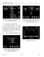
Fig. 4-10.
Firing in manual screen.
Fig. 4-11.
Dry shut down screen.
Содержание Steam Master CSMG-15
Страница 1: ...STEAM MASTER SERIES USER MANUAL Cover CSMG 15 30 40 R027880B 20190603 ...
Страница 8: ...vi The controls and features may differ depending on the unit s size and specifications ...
Страница 9: ...vii The controls and features may differ depending on the unit s size and specifications ...
Страница 14: ...Specifications_CSM_a fm xii 11 22 2018 This page intentionally left blank ...
Страница 26: ...Sect02_CSMG_b fm 2 6 04 19 2019 Steam Master Instruction Manual This page intentionally left blank ...
Страница 44: ...Sect05_CSMG_a fm 5 6 11 26 2018 Steam Master Instruction Manual NOTES ...
Страница 56: ...Sect06_CSMG_b fm 6 12 04 22 2019 Steam Master Instruction Manual This page intentionally left blank ...
Страница 66: ...Sect07_CSMG_b fm 7 10 04 26 2019 Steam Master Instruction Manual This page intentionally left blank ...
Страница 68: ...HeatingSect_SM15_a fm A 2 04 30 2019 Fig 01A Main Heating Section SM15 ...
Страница 69: ...04 30 2019 A 3 HeatingSect_SM15_a fm FIG 01A Main Heating Section SM15 ...
Страница 70: ...HeatingSect_SM15_a fm A 4 04 30 2019 Fig 01B Economizer Stack Outlet Kit SM15 ...
Страница 71: ...04 30 2019 A 5 HeatingSect_SM15_a fm FIG 01B Economizer Stack Outlet Kit SM15 ...
Страница 72: ...HeatingSect_SM30_b fm A 6 12 05 2018 Fig 01C Main Heating Section SM30 ...
Страница 73: ...12 05 2018 A 7 HeatingSect_SM30_b fm FIG 01C Main Heating Section SM30 ...
Страница 74: ...HeatingSect_SM30_b fm A 8 12 05 2018 Fig 01D Economizer Coil SM30 ...
Страница 75: ...12 05 2018 A 9 HeatingSect_SM30_b fm FIG 01D Economizer Coil SM30 ...
Страница 76: ...HeatingSect_SM45_b fm A 10 04 30 2019 Fig 01C Main Heating Section SM40 ...
Страница 77: ...04 30 2019 A 11 HeatingSect_SM45_b fm FIG 01C Main Heating Section SM40 ...
Страница 78: ...HeatingSect_SM45_b fm A 12 04 30 2019 Fig 01D Economizer Coil SM40 Sht 1 of 2 ...
Страница 79: ...04 30 2019 A 13 HeatingSect_SM45_b fm FIG 01D Economizer Coil SM40 ...
Страница 80: ...Sep Trap PressMfld_SM153040_b fm A 14 04 30 2019 Fig 02A Steam Discharge and Separator Hookup SM 15 ...
Страница 81: ...04 30 2019 A 15 Sep Trap PressMfld_SM153040_b fm FIG 02A Steam Discharge and Separator Hookup SM 15 ...
Страница 82: ...Sep Trap PressMfld_SM153040_b fm A 16 04 30 2019 Fig 02B Steam Discharge and Separator Hookup SM 30 40 ...
Страница 83: ...04 30 2019 A 17 Sep Trap PressMfld_SM153040_b fm FIG 02B Steam Discharge and Separator Hookup SM 30 40 ...
Страница 86: ...Sep Trap PressMfld_SM153040_b fm A 20 04 30 2019 Fig 02E Pressure Indicating System ...
Страница 87: ...04 30 2019 A 21 Sep Trap PressMfld_SM153040_b fm FIG 02E Pressure Indicating System ...
Страница 90: ...PumpHkup C1 C2_parts_a fm A 24 03 05 2019 Fig 05A Pump Assy C1 ...
Страница 91: ...03 05 2019 A 25 PumpHkup C1 C2_parts_a fm FIG 05A Pump Assy C1 ...
Страница 92: ...03 05 2019 A 26 PumpHkup C1 C2_parts_a fm Fig 05B Pump Assy C2 ...
Страница 93: ...PumpHkup C1 C2_parts_a fm A 27 03 05 2019 FIG 05B Pump Assy C2 ...
Страница 98: ...Blank_Left fm A 32 08 16 2017 This page intentionally left blank ...
Страница 104: ...25 75 bhp Feedwater Skid Option FeedwtrSkid_VHtwl_25 75bhp_a fm B 6 11 26 2018 This page intentionally left blank ...
Страница 106: ...R027906A 2018 10 22 ...
Страница 107: ...NOTES ...
Страница 108: ...Steam Generator Instruction Manual This page intentionally left blank ...
Страница 109: ......


