ASSEMBLY
CAUTION!
ASSISTANCE MUST BE USED WHEN ASSEMBLING THIS MACHINE.
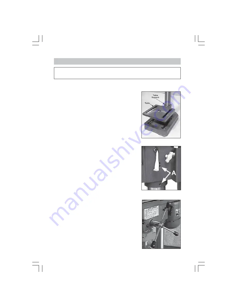
Fig. 1
Fig. 3
A. Column to the Base.
Bolt the column assembly to the base with the four M10 x
40mm hex. screws provided.
NOTE:
Ideally - the base, with column attached, should be
firmly bolted to the floor or workbench prior to the assembly
of other components.
Check to ensure the column securing set screws, at the
column support, are tight.
B. Table to Column.
1.
Thread the Table Support Locking Handle (see Fig. 7),
into the Table Support from the left hand side, and
leave it loose at this stage.
2.
Slide the Table Support with Table, over the Column
and lower it so that it rests against the column support
bracket (Fig. 1). Nip up the locking handle to prevent
the table from swinging freely during the
assembly process.
C. Head to Column.
NOTE:
I
t may be necessary to unscrew the Head Lock Set
Screws, (A -Fig.2), to ensure they do not protrude internally,
as this would prevent the head from sliding fully into
position.
1.
With assistance, raise the Head and locate it on top of
the Column, ensuring it slides home fully.
2.
Align the head with the base and tighten down the
Head Lock Set Screws using the wrench provided.
3.
Locate the three feed handles, and screw them firmly
into the hub of the feed shaft Fig.3.
Fig. 2
D. Chuck Guard Assembly
Slide the Chuck Guard over the Quill Shaft and nip up the
pinch bolt, temporarily, with the pinch bolt facing the front,
(see Fig. 4). Ensure the Quill Shaft/Spindle is at the top of its
travel.
NOTE:
This operation should be carried out before the chuck
is installed.
9
Содержание METALWORKER CDP201B
Страница 1: ...0307 SERIAL No ...
Страница 18: ...HEAD ASSEMBLY 18 ...


