background image

Page    -26-


                  Clarke

®

 Operator's Manual  -Encore S17/L17

NOTE

S

Содержание Encore l17

Страница 1: ...must have training in the operation of this machine before using it If operator s cannot read this manual have it explained fully before attempting to operate this machine Si Ud o sus operadores no pueden leer el Inglés se hagan explicar este manual completamente antes de tratar el manejo o servicio de esta máquina All directions given in this book are as seen from the operator s position at the r...

Страница 2: ...ction Diagram 55 Encore L17 Electrical Schematic 56 Operator Safety Instructions 3 Machine Introduction 4 Machine Specifications 5 Procedures for Transporting Machine 6 Symbols Used on Encore S17 and L17 8 Machine Control Panel 10 Machine Controls and Features 11 How to Prepare the Machine for Operation 12 How to Install the Batteries 12 Battery Maintenance 14 How to Charge the Batteries 15 How to...

Страница 3: ...s grain dust solvents thinners or other flammable materials This machine is not suitable for picking up hazardous dust Use only commercially available floor cleaning chemicals intended for machine application DANGER Lead acid batteries generate gases which can cause an explosion Keep sparks and flames away from batteries Do not smoke around the machine Charge the batteries only in an area with goo...

Страница 4: ...water may damage the environment and be illegal The United States Environmental Protection Agency has established certain regulations regarding discharge of waste water City state and national regulations regarding this discharge may also be in effect in your area Understand and follow the regulations in your area Be aware of the environment hazards of chemicals that you dispose WARNING Only use t...

Страница 5: ...AH 454 lbs 206 kg 472 lbs 214 kg Line of Sight Operator Height 5 8 7 5 feet 2 3 m Warranty Machine 3 Years Polydur tanks 8 Years Batteries 18 Months Pro rated Encore L17 Rotary Model Encore S17 Cylindrical Machine Power Supply 24 Volt D C 2 12V 130AH Wet 24 Volt D C 2 12V 130AH Wet or 2 12V 100AH Gel Deep Cycle Batteries or 2 12V 100AH Gel Deep Cycle Batteries Traverse Not Applicable 1 3 HP 0 25 k...

Страница 6: ...the loading ramp is at least eight 8 feet 2 5m long and a minimum of 32 0 8m wide and strong enough to support the machine 2 Make sure the ramp is clean and dry 3 Put the ramp in position 4 Removesqueegeeassembly brushhousingand brush or pad driver before loading Clarke recommends that both the solution tank and recovery tank are empty before loading 5 On the L17 models only turn the key switch ON...

Страница 7: ...e machine is heavy Make sure you use two able persons to assist in moving the machine down the ramp 6 On S17 model get two people to pull machine off ramp It is recommended that the S model be unloaded in the forward position 7 On the L17 models only turn the key switch ON and press the green ON button 8 Set the traverse center knob to the slowest forward speed setting Carefully and slowly drive t...

Страница 8: ...Page 8 Clarke Operator s Manual Encore S17 L17 SYMBOLS USED ON ENCORE S17 and L17 Solution Control BrushUp Down Vacuum SqueegeeControl Warning Power Traverse Speed Control LClass only Battery Meter ...

Страница 9: ...Clarke Operator s Manual Encore S17 L17 Page 9 SYMBOLS USED ON ENCORE S17 and L17 Warning Label with parking brake Warning Label without parking brake AC Power Indicator ...

Страница 10: ... primarily for preventing unauthorized use by removing the key To turn the control panel ON the key switch must be turned clockwise and then the green ON button must be pressed see item C To turn the control panel OFF turn the key switch counterclock wise ON OFF Buttons See Figure 3 Item C Pressing the green button turns ON the power to the control panel if the machine is equipped with a key switc...

Страница 11: ...motor is turned on when the handle is lowered to either the center or lowest position Float Shut Off See Figure 6 The shut off switch for the vacuum motor is located in the recovery tank It automatically turns off the vacuum motor when the recovery tank is full NOTE If excessive foaming occurs in recovery tank defoamer must be added Damage to vacuum motor could result from foam entering into the v...

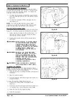
Страница 12: ... Unhooktherecoverytankdrainhosevalvefrom it s hanger bracket and lay the loose end on the floor Seefigure8 WARNING Before raising or removing the recovery tank be sure tank is empty Do not operate or per form maintenance on the ma chine while the recovery tank is in the open position The tank can be accidentally bumped and it may slam shut 5 Disconnect the blue electrical float connector See Figur...

Страница 13: ...covery tank is installed under the metal plate on the solution tank See figure 13A 13 Reattach the tether to the recovery tank See figure10 WARNING The recovery tank can fall off of the machine when open ing the tank or operating the machine if the recovery tank is not properly installed Make sure that the recovery tank pivot pin is under the metal plate on the solution tank and the tether is at t...

Страница 14: ...n occur if the batteries are over filled Do not fill the batteries up to the bottom of the tube in each cell Wipe any acid from the machine or the tops of the batteries Never add acid to a battery after installation CAUTION Batteries must be refilled with distilled water only Do not use tap water as it may contain contami nants that will damage batteries 2 Keep the tops of the batteries clean and ...

Страница 15: ...very tank be sure tank is empty Do not operate or perform maintenance on the machine while the recovery tank is in the open position The tank can be accidentally bumped and it may slamshut 5 The Encore 17 is equipped with an on board charger located behind the recovery tank See Figure 17 The charger is a 3 stage charger designed to maximize battery life The AC power cord to the on board charger is...

Страница 16: ...ng assembly pull outward on the spring loaded pin on the left side of the housing then lift the brush housing assembly up and outward See Figure 18 Reinstall the brush housing assembly in reverse order making sure the cross bar in the brush housing is inserted into the two slots located in the motor mount and the spring loaded pin is locked into position See Figure 19 How To Install Rotary Brush o...

Страница 17: ...button 2 Raise the brush head by pressing and holding the brush up switch until brush head is in it s full up and rotatedposition 3 Press the red OFF button or turn the key switch counterclockwise on machines equipped with key 4 Gotofrontofthemachineandremovethumbscrew from brush door See Figure 22 5 Lower door approximately 1 2 inch and slide door and bearing assembly off shaft See Figure 23 6 Re...

Страница 18: ...on tank with water WARNING Water solutions or cleaning materi als used with this type of machine can leave wet areas on the floor surface These areas can cause a dangerous condition for the operator or other persons Always put CAUTION signs near the area you are cleaning WARNING Machines can ignite flammable materials and vapors Do not use with or near flammables such as gasoline grain dust solven...

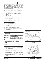
Страница 19: ...erator or other persons Always put CAUTION signs near the area you are cleaning To clean a floor follow this procedure 1 Set the parking brake if equipped with machine 2 Put the water and a cleaning chemical in the clean solution tank 3 Release the parking brake if equipped with machine 4 Turn the key switch clockwise to the ON position L models only Press the green ON button 5 Lower the squeegee ...

Страница 20: ... Dirty Floor To clean a very dirty floor follow this procedure 1 Apply solution to the floor 2 Do not lower the squeegee This will keep the vacuum motor off 3 Lower the brush or pad and scrub the floor 4 Scrub the floor again with additional solution and lower the squeegee 5 Pick up all the solution with the squeegee WARNING Maintenance and repairs must be done by authorizedpersonnelonly WARNING A...

Страница 21: ...thebackofthe machine c Put the end of the hose over a drain or bucket d Recovery Tank 1 Turn the valve housing to the left See Figure33 2 To open the valve completely turn the housingfullytotheleft Pullthehousing offofthevalve Figure34 e Solution Tank When hose is lowered below water level water will flow 2 Flush the tanks To flush the tanks put clean water in the tank through the opening on top o...

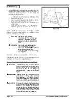
Страница 22: ...TILLED WATER ONLY WARNING Lead acid batteries generate gases which can cause an explosion NO SMOKING Always wear eye protection and protective clothing when working near batteries Use a clean cloth and wipe the surface of the machine Charge the batteries See the instructions in the section of this book called How To Charge The Batteries Maintenance Procedures To Be Done Every Week WARNING Maintena...

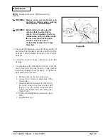
Страница 23: ...rbonate of soda to wipe the top of the batteries Clean the battery terminals Reconnect the batteries 2 Check the hoses for leaks obstructions and other damage 3 On machines with cylindrical brush head check the brush drive belts for proper tension Belts must be tensioned properly to prevent slipping To tighten the belts follow this procedure a Removebeltcoverbyremovingscrews b Loosen the 2 screws ...

Страница 24: ...tment Adjusting Squeegee Tilt The tilt of the squeegee causes the rear blade to raise up in the center or on the ends depending on which direction the tilt is changed For tilt adjustment refer to figure 38 Loosen left and right screw X In order to bring the blades down in the center tip Y down To bring both ends down tip Y up Make very small adjustments and try it until a uniform flare is achieved...

Страница 25: ...shes and Pad Assemblies Size Description Part No 17 Pad Driver Asm 10405A 17 Polypropylene 52539A 17 Nylon 52540A 17 Lite Grit 52543A 17 CleanGrit 52541A CylindricalBrushes Size Description Part No 4 Polypropylene 30231A 4 Nylon 30232A 4 CleanGrit 30233A 4 SuperGrit 30234A 29 Squeegee Blades Description Part No Blade Rear Gum Rubber 30931A Blade Rear Nitrile Solid 30938A Blade Front Ribbed Urethan...

Страница 26: ...Page 26 Clarke Operator s Manual Encore S17 L17 NOTES ...

Страница 27: ...Clarke Operator s Manual Encore S17 L17 Page 27 ENCORE S17 L17 Section II Parts and Service Manual 70483A U S Patent No 5 383 251 6 105 192 No 6 557 207 No 6 760 947 and other Patents Pending ...

Страница 28: ...e the batteries Charge the batteries for a full 16 hour charge Have an authorized service person repair the charger Check voltage of each cell while discharging Connect the batteries Adjust Pressure PROBLEM CAUSE ACTION The solution tank is empty There is an obstruction in the solution hose or filter The solution valve or electric wiring is damaged The control module is defective The solution valv...

Страница 29: ...itch is off Batteries are disconnected Battery terminals are dirty Batteries are discharged Reset the circuit breaker Turn key or switch on Check the battery connections Check battery meter and recharge NOTE If the problem continues consult an authorized service person Replace the scrub brush or pad Have an authorized service person make the needed repairs Check for tripped breaker Reset Check for...

Страница 30: ...Page 30 Clarke Operator s Manual Encore S17 L17 1 2 3 4 5 6 7 2 8 9 10 11 12 2 3 13 14 12 Clarke Encore S17 L17 S17 L17 Cylindrical Final Assembly 11 02 3 2 16 15 12 ...

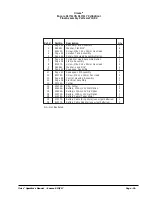
Страница 31: ...ck 5 16 4 10 Page 42 Squeegee Assembly 1 11 Page 40 Squeegee Lift Assembly 1 12 80179A Screw M6 x 1 x 15mm Pan Head 6 13 Page 38 Control Housing Assembly 1 14 Page 36 Electrical Assembly 1 15 30334A Tether 1 16 52570A Clip Tether 1 NI 40606A Battery 130AH 12V Wet Option 2 NI 40605A Battery 130AH 12V Dry Option 2 NI 40070A Battery 100AH 12V Gel Option 2 NI 41206A Battery Cable Taper Style 1 NI 4121...

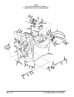
Страница 32: ...2 Clarke Operator s Manual Encore S17 L17 Clarke Encore S17 L17 S17 L17 Cylindrical Recovery Tank Assembly 5 03 1 2 3 4 5 6 6A 6B 6C 7 8 9 10 11 12 13 14 15 14 16 17 18 19 20 21 22 18 23 24 25 26 27 28 29 30 ...

Страница 33: ...k 1 8 30227A DrainHousing 1 9 30226A DrainPlug 1 10 52560A O Ring 1 11 30225A DrainBody 1 12 82100A Locknut 1 2 Conduit 1 13 872102 Nylon Clip 5 16 OD 2 14 962957 Screw 10 16 x 1 2 2 15 52206A Chain 1 16 43402A Housing Connector included in 6A 2 17 41809A Contact included in 6A 2 18 80193A Screw M5 x 8 x 10mm Pan Head 4 19 832002 DrainValveClamp 1 20 35102A DrainHose 1 21 61459A Latch Plate 1 22 9...

Страница 34: ... S17 L17 Clarke Encore S17 L17 S17 L17 Cylindrical Solution Tank Front Cover Assembly 9 04 1 3 4 5 6 7 2 6 2 7 8 9 12 2 6 13 14 15 16 3 17 18 19 20 21 22 23 24 26 21 28 27 21 23 32 33 34 35 2 36 12 6 37 38 39 14 40 41 42 43 45 39 44 46 2 47 ...

Страница 35: ...et 1 20 30219A SolutionTank 1 21 50248A HoseClamp 6 22 53607A Elbow 1 4 NPT x 3 8 1 23 30172A Hose 2 24 51204A Valve Solution 1 26 820207 Adapter 1 27 30453A Hose 1 28 59614A BatteryDrainValve 1 32 51518A Bushing 2 33 51526A Hosebarb 3 8 x 90 2 34 55189A Hosebarb 1 2 x 90 2 35 31242A Bushing 2 36 30239A Level DrainHose 1 37 30222A Solution Lid 1 38 61280A DrainHoseHanger 1 39 980603 Lock Washer 10...

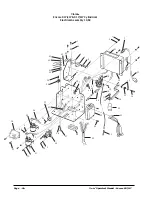
Страница 36: ...7 L17 Clarke Encore S17 L17 S17 L17 Cylindrical Electrical Assembly 11 02 1 2 3 4 5 6 2 1 7 8 9 10 11 12 13 14 15 16 17 18 19 20 21 22 23 24 25 26 27 28 29 2 30 31 2 30 33 32 2 30 34 35 36 37 24 38 39 40 41 40 41 42 43 44 45 7 46 47 48 49 51 50 ...

Страница 37: ... 1 21 40631A Traverse Harness 1 22 80186A Eyebolt 10 24 1 1 23 40592A Traverse Controller 1 24 80221A Screw M4 x 7 x 20mm Pan Head 3 3 25 40630A Main Harness Traverse 1 40629A Main Harness Non Traverse 1 26 193951 Grommet 8 5 1 1 27 80205A Screw M5 x 8 x 20mm Pan Head 1 1 28 80204A Nut M3 x 5 Nylock 2 2 29 40169A Solenoid Vacuum 1 1 30 80208A Screw M6 x 1 x 10mm Pan Head 6 6 31 41811A Contactor Ma...

Страница 38: ... Clarke Operator s Manual Encore S17 L17 Clarke Encore S17 L17 S17 L17 Cylindrical Control Housing Assembly 7 03 1 3 4 5 6 7 8 9 10 11 12 13 15 17 16 18 19 20 21 23 24 23 25 20B 22 26 27 28 29 1 30 31 14 33 32 ...

Страница 39: ... 2 2 2 2 15 980608 Washer Flat 6 4 4 4 4 16 40126A Switch Assembly 2 2 2 2 17 80191A Screw M3 5 x 6 x 10mm Pan Head 4 4 4 4 18 52556A ReverseSwitch 1 1 19 30220A ControlHandle Traverse 1 1 30228A ControlHandle Non Traverse 1 1 20 47380A Key Switch 1 1 20B 55413A Key Spare 1 1 21 80230A Washer Nylon 1 1 22 87052A Washer Key Switch 1 1 23 41422A Circuit Breaker 25A 1 2 2 3 24 41433A Circuit Breaker ...

Страница 40: ...Page 40 Clarke Operator s Manual Encore S17 L17 Clarke Encore S17 L17 S17 L17 Cylindrical Squeegee Lift Assembly 11 02 1 2 3 4 5 6 7 8 9 10 11 12 13 5 14 15 16 11 17 7 8 ...

Страница 41: ...ck 5 16 1 7 80195A Screw M6 x 1 x 20mm Hex Head 4 8 87026A Washer Flat 1 4 2 9 61292A Pin Bracket 1 10 61296A SqueegeeArm 1 11 980651 Washer Flat 5 16 2 12 80194A Screw M8 x 1 25 x 30mm Hex Head 1 13 80101A Screw 1 4 20 x 3 1 4 1 14 61461A SqueegeeSwivelSpacer 1 15 60256A Pivot Bracket 1 16 80197A Screw M8 x 1 25 x 20mm Hex Head 1 17 81104A Nut 1 4 20 Nylock 1 Clarke Encore S17 L17 S17 L17 Cylindr...

Страница 42: ...Page 42 Clarke Operator s Manual Encore S17 L17 Clarke Encore S17 L17 S17 L17 Cylindrical 32 Squeegee Assembly 6 04 1 2 21 21 3 4 5 4 5 20 19 18 7 8 17 21 9 10 11 12 13 14 15 16 22 ...

Страница 43: ... 2 7 50958A Ring 3 8 ID Snap 2 8 30048A Wheel Guide 4 Inch Diameter 2 9 60234A Channel SqueegeeWeldment32 1 10 50835A Latch SqueegeeClamp 1 11 930086 Rivet 3 16 x 450 Aluminum 2 12 60232A Strap Clamp Squeegee Retainer 32 1 13 30067A Blade Rear Gum Rubber 32 1 14 30047A Spacer Squeegee32 1 15 30066A Blade Front Ribbed 32 1 16 80011A Screw 3 8 16 x 3 2 17 81301A Nut 3 8 16 Jam SS 2 18 34260B Gasket ...

Страница 44: ...L17 Clarke Encore S17 L17 S17 L17 Cylindrical Frame Assembly 9 03 1 2 3 4 5 7 8 9 10 11 2 1 13 12 10 11 14 12 15 2 17 1 19 18 20 21 22 15 23A 12 24 25 26 27A 28 24 12 29 27B 2 30 23B 12 24 12 12 31 32 12 31 33 31 12 1 2 34 24 1 35 36 37 38 16 12 ...

Страница 45: ... 80195A Screw M6 x 1 x 20mm Hex Head 2 3 2 3 16 980614 Washer Lock 1 4 Ext Tooth 2 2 17 61302A Static Strap 1 1 18 47422B Switch Wisker 1 1 1 1 19 80203A Screw M3 x 5 x 30mm Pan Head 2 2 2 2 20 59610A SolutionValve 1 1 1 1 21 51526A Hosebarb 90 3 8 x 3 8 1 1 52635A Hosebarb 90 3 8 x 1 2 1 1 22 30311A Hose 1 1 23A 61455A Axle Non Traverse 1 1 23B 61076A Transaxle 1 1 24 80197A Screw M8 x 1 25 x 20m...

Страница 46: ...7 Cylindrical Cylindrical Head Assembly 7 03 1 2 3 4 5 3 6 7 7 6 8 9 4 5 3 59 11 12 13 14 15 16 17 18 19 20 21 22 10 23 24 25 6 26 27 28 29 7 30 34 33 32 29 7 35 3 36 37 25 38 3 6 39 40 20 29 41 44 42 43 10 45 16 46 25 47 48 49 10 50 51 52 53 54 55 56 57 10 31 58 58 60 ...

Страница 47: ... 25 53399A Flange Bearing 4 26 80179A Screw M6 x 1 x 15mm Pan Hd 4 27 61282A Cover L H Belt 1 28 80214A Screw M6 x 1 x 12 Hex Head 2 29 980657 Washer 1 4 Lock 10 30 61396A Motor Pulley 2 31 21058A Brush Housing 1 32 57994A Screw M6 x 20mm Hex Head 4 33 61397A Brush Pulley 2 34 52818A Drive Belt 2 35 80178A Shoulder Bolt M6 x 8 x 30mm 2 36 59932A Front Wheel 2 37 80187A Bolt M8 x 1 25 x 30mm Hex Hd...

Страница 48: ... 48 Clarke Operator s Manual Encore S17 L17 Clarke EncoreS17 L17 Rotary Disk Head Assembly 9 03 1 2 3 4 5 6 7 8 9 10 11 12 13 14 15 16 17 18 19 20 21 22 23 24 25 26 27 28 29 30 9 31 7 8 11 6 5 9 34 33 32 35 ...

Страница 49: ...A Motor Mount Bracket 1 1 14 98451A Washer Lock 7 16 4 4 15 80184A Bolt M10 x 1 5 x 25mm Hex Head 4 4 16 20308A MotorAdaptor 1 1 17 980679 Washer Flat 3 4 1 1 18 980210 Washer Impeller 1 1 19 980652 Washer Lock 5 16 1 1 20 80197A Screw M8 x 1 25 x 20mm Hex Head 1 1 21 30216A UpperBrushHousing 1 1 22 30217A LowerBrushHousing 1 1 23 70667A Label 17 1 1 24 66550A Pin Assembly 1 1 25 80224A Shoulder B...

Страница 50: ...Assembly and Parts List 5 03 Ref Part No Description Qty 1 57846A Ring Snap 1 2 507641 Seal Oil Small 1 3 52050A CapEnd 1 4 56668A O Ring 1 5 51176A Bearing Large 1 7 902605 Bearing Small 1 9 58144A Seal Oil Large 1 10 NI Darina EP2 Grease 4 oz 11 52855A Complete Gearbox Asm 1 1 2 3 4 5 7 8 ...

Страница 51: ...r Bracket 1 7 56480A Strain Relief 2 8 962546 Brush Board Screw 2 9 50517A Brush Board Assembly w Springs Brushes 1 10 448396 Brush Spring 4 11 40826A Brush Assembly 4 12 55657A Lead Assembly 1 13 55656A Lead Assembly 1 14 Helical Washer 1 15 50515A Thru Bolt 2 16 80501A Shaft Key 1 17 54238A B E Bracket Assembly Gear Box 1 13 SeamLocation 7 12 15 4 5 6 1 2 3 14 16 17 12 13 8 9 10 11 NOTE Parts no...

Страница 52: ...2 BLK RED 1 2 3 4 5 6 Item Part No Description Qty 1 10135A Wheel Flange Kit 2 2 51056A Transaxle Mounting Sleeve 2 3 40593A Motor Brush 2 4 40594A Motor Urethane Sleeve 1 5 40595A Motor 1 6 40596A Transaxle Only 1 Specifications Motor 24VDC Permanent Magnet Tenv Transaxle 30 1 Ratio Gear Oil Mobile SHC634 12 oz ...

Страница 53: ...Clarke Operator s Manual Encore S17 L17 Page 53 Clarke Encore S17 Connection Diagram 12 02 BLK RED RED YEL ...

Страница 54: ...Page 54 Clarke Operator s Manual Encore S17 L17 Clarke Encore S17 Electrical Schematic 11 02 ...

Страница 55: ...Clarke Operator s Manual Encore S17 L17 Page 55 Clarke EncoreL17 Connection Diagram 12 02 RED YEL BLK RED ...

Страница 56: ...Page 56 Clarke Operator s Manual Encore S17 L17 Clarke EncoreL17 Electrical Schematic 11 02 ...

Страница 57: ... Hardinxveld Giessendam The Netherlands 31 184 677 200 ALTO Sverige AB Molndal Sweden Aminogatan 18 Box 4029 S 431 04 Molndal 46 31 706 73 00 ALTO Norge A S Oslo Norway Bjornerudveien 24 N 1266 47 2275 1770 U S A Locations European Locations CORPO PRODUCTION FACILITIES Clarke Springdale Arkansas 2100 Highway 265 Springdale Arkansas 72764 479 750 1000 Customer Service 1 800 253 0367 Technical Servi...

Страница 58: ...D RECOVERY TANK EIGHT YEAR U S GUARANTEE Your new Clarke machine has polydur Solution and Recovery Tanks Polydur is a rotationally molded low density linear polyethylene that won t crack or dent and withstands most corrosives and temperature extremes Clarke backs up your Polydur tanks with an eight year guarantee If a tank breaks or leaks under normal use within eight years of the date of purchase...

Отзывы: