


Service Manual-CA60 14 Wheel System 22
14 Wheel System, Traction
Functional Description
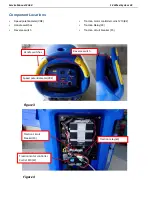
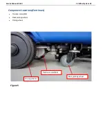
Machine movement is provided by the traction motor (M3) (except CA60 20D).
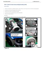
The traction motor unit (M3) also functions as the main support of the machine, and is composed of an electric
motor, the reduction unit with differential and the drive wheels.
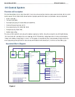
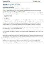
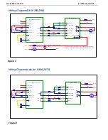
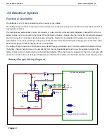
The main controller (E1) energizes the K3 traction relay to power up the Curtis 1210 drive wheel controller (E2).The
drive wheel controller regulates the traction motor direction and speed based on inputs from the following inputs:
Speed POT, Pin J1-18
POT Wiper, Pin J1-4
Reverse J1-17
Forward is performed by pressing one of the two handle switches (SW1 or SW2). In response, the main control board
closes an internal switch, shown in the diagram below, which connects the speed pot wiper circuit through the main
control board and out to the speed controller POT Wiper input, PIN J1-4. This is a variable voltage input which is
dependent on the speed pot position and serves as an input request for the drive wheel controller to propel the
machine. A higher voltage input is a request for more speed and a lower input is a request for a slower speed.
Regulation of the maximum speed can be set with the knob (hare / tortoise) on the Main Control Board (E1). which
are connected directly to the speed potentiometer (VR2).
Reverse is performed by pressing the reverse switch (SW3) and one of the two handle switches (SW1 or SW2) at the
same time.
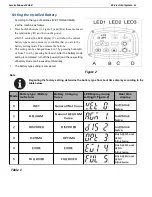
When the battery voltage is lower than 18V, the main control board opens its internal switch in series with the POT
wiper circuit which disables the drive wheel operation. The battery must be charged before operation is restored. An
the LED digital display will show error message
”
LO-18
”
.
The propel speed is reduced when scrubbing. When the scrub brush motor is turned on, by energizing the K1
contactor, it removes the battery voltage input from the speed mode input J1-8, which the controller interprets as a
request for low speed operation. It responds by reducing the propel speed.
Содержание CA60 20B
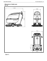
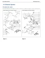
Страница 15: ...Service Manual CA60 03 General Information 12 Dimensions Continues CA60 20D CA60 20TD Figure 4...
Страница 16: ...Service Manual CA60 03 General Information 13 Dimensions Continues CA60 20B Figure 5...
Страница 17: ...Service Manual CA60 03 General Information 14 Dimensions Continues CA60 24B Figure 6...


