Clarke Air CAT159 Скачать руководство пользователя страница 5

5

Parts & Service: 020 8988 7400 / E-mail: [email protected] or [email protected]
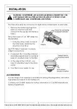
INSTALLATION

The filter will usually be connected to rigid airline components to each side.

1. Remove the blanking plugs from 

each connection port and 
connect to the supply and delivery 
hoses.

Note that a pair of 1/4” BSP adaptors 
are supplied.

• Note the arrow mark on top of 

the filter body, indicates the 
direction of air flow.

Use PTFE tape if required, to ensure 
airtight connections.

2. If required, fit a mounting bracket 

(available separately) to a suitable 
support, situated close to the filter.

3. In the case of the CAT169, you 

may fit a flexible hose to the drain 
outlet.

4. Your filter is now ready for use.

ACCESSORIES

A wide range of accessories is available including filter/regulators, lubricators, 
high-pressure hoses (5 to 50 metres) etc.

Contact your CLARKE dealer for further information or CLARKE International 
Service Department.

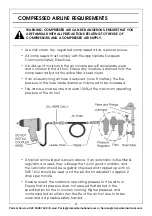
WARNING: COMPRESSED AIR CAN BE DANGEROUS. ENSURE THAT YOU 
ARE FAMILIAR WITH ALL PRECAUTIONS RELATING TO THE USE OF AIR 
COMPRESSORS AND COMPRESSED AIR SYSTEMS.

Содержание Air CAT159

Страница 1: ...INSTALLATION MAINTENANCE INSTRUCTIONS ORIGINAL INSTRUCTIONS GC0217 AIR FILTER MODEL NO CAT159 CAT169 PART NO 3120173 3120183...

Страница 2: ...ward to your purchase giving you long and satisfactory service Your air filter has been designed to give long and trouble free service If however having followed the instructions in this booklet caref...

Страница 3: ...gs or medication 2 Do not overreach when using air tools Keep proper footing and balance at all times 3 Never use oxygen CO2 combustible gasses or any type of bottled gas as a source of power for air...

Страница 4: ...ose must be rated at least 150 of the maximum operating pressure of the air tool A typical air line layout is shown above If an automatic in line filter regulator are used they will keep the tool in g...

Страница 5: ...required to ensure airtight connections 2 If required fit a mounting bracket available separately to a suitable support situated close to the filter 3 In the case of the CAT169 you may fit a flexible...

Страница 6: ...l resistance from the O ring NOTE In the case of the CAT159 the bowl and bowl cover will remain connected by the drain tap 5 The clear bowl and filter element can then be washed out before re assembly...

Страница 7: ...keinternational com PARTS LIST DIAGRAM Ref No Description 1 Main Housing 2 Baffle 3 Screw Arbor 4 Filter Element 5 Baffle Board 6 Drain Valve Seat 7 O Ring 8 Inner Bowl 9 Outer Bowl 10 Spring 11 Trigg...

Страница 8: ......

Отзывы: