OPERATING & MAINTENANCE
INSTRUCTIONS
0410
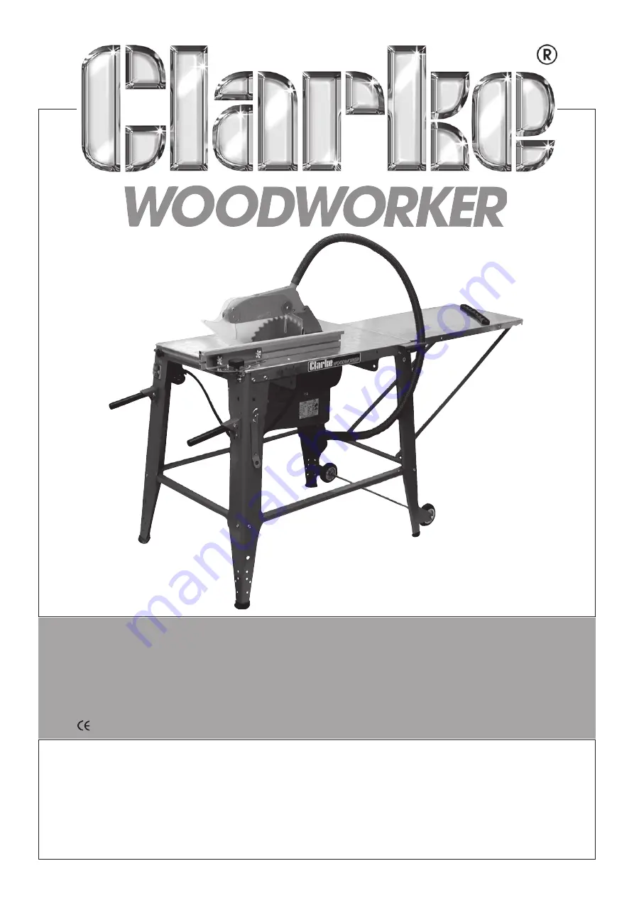
Model No. CCS12
Part No. 6460000
12in (305mm)
CONTRACTOR’S SAW
Serial/Batch No:
................................
Страница 1: ...OPERATING MAINTENANCE INSTRUCTIONS 0410 Model No CCS12 Part No 6460000 12in 305mm CONTRACTOR S SAW 12in 305mm CONTRACTOR S SAW Serial Batch No...
Страница 2: ...ing numbers PARTS SERVICE TEL 020 8988 7400 PARTS SERVICE FAX 020 8558 3622 or e mail as follows PARTS Parts clarkeinternational com SERVICE Service clarkeinternational com PARTS SERVICE CONTACTS 2 WA...
Страница 3: ...arantee is invalid if the product is found to have been abused or tampered with in any way or not used for the purpose for which it was intended Faulty goods should be returned to their place of purch...
Страница 4: ...tments or when changing accessories such as blades etc DON T FORCE THE MACHINE It will do a better and safer job at the rate for which it was designed AVOID DANGEROUS ENVIRONMENTS Don t use power mach...
Страница 5: ...chine Consult your local dealer BE AWARE that accidents are caused by carelessness due to familiarity ALWAYS concentrate on the job in hand no matter how trivial it may seem HANDLE WITH EXTREME CARE W...
Страница 6: ...s removed They must all be in place and securely fastened when performing any operation Use ONLY approved replacement saw blades Contact your local CLARKE dealer for advice The use of inferior blades...
Страница 7: ...ade may tilt by up to 45 in one direction It is then secured in position by tightening the same knobs Extending from the front end of the box is a handle used for raising and lowering the blade and is...
Страница 8: ...Q Dust Extractor Hose Bkt 1 R End Cap for Knob Item S 2 S Knob Assy for Rip Fence Guide 2 U Rubber Washer 2 V Leg 4 W Table Extension Brace 2 X Short Leg Brace 2 Y Long Leg Brace 2 Z Rip Fence Mitre...
Страница 9: ...Extraction Hose D 10 Dust Extractor Outlet E 11 DustExtractionHoseBracket Q 12 Motor 13 Lower Blade Guard Box 14 Table Extension AA 15 Table Extension Brace Y 16 Long Leg Brace W 17 Short Leg Brace X...
Страница 10: ...facing the table and open angle facing the feet and the two shorter leg Braces in a similar manner ASSEMBLY Unless otherwise specified DO NOT fully tighten the fixing nuts during assembly Due to the...
Страница 11: ...le proceed to tighten all fixing nuts securely Ensure the table extension top and the table top lie in the same plane before securing the fixing bolts F The Riving Knife 12 Remove the Table insert sec...
Страница 12: ...lade Guard then secure the Upper Blade Guard to the Riving Knife using the same bolt screwed into the nut held in a recess in the blade guard The nut and end of the bolt is arrowed in Fig 9 WARNING Th...
Страница 13: ...le in the table top see Fig 11 then through the Rip Fence Guide Press a nut into the hex depression within the Clamping Knob and then thread the nut with the knob on to the coach bolt as shown in Fig...
Страница 14: ...ghten ensuring the handles are free to raise and lower smoothly L Tool Hook 20 Attach the Rip Fence Support E to the underside of the quadrant as shown so that the post on the support protrudes throug...
Страница 15: ...YELLOW Connect BROWN coloured cord to plug terminal marked with a letter L or coloured RED Connect BLUE coloured cord to plug terminal marked with a letter N or coloured BLACK If this appliance is fit...
Страница 16: ...use i e BEFORE connecting the machine to the mains supply A The Riving Knife is essential in preventing kickback and hence the risk of personal injury and producing a good clean cut without chattering...
Страница 17: ...e feed force should ALWAYS be applied between the saw blade and the fence and down on to the table NOT on the section that will become the cut off piece Always use a push stick when the end of the wor...
Страница 18: ...roceeding MAINTENANCE 1 GENERAL Maintenance is limited to changing the saw blade when necessary maintaining adjustments and ensuring that after use any sawdust or wood chips are cleaned away using a l...
Страница 19: ...cessary for it to be moved outwards away from its mounting bracket slightly For this purpose two 1mm shims are provided and should be fitted as follows NOTE One or both of the shims may be used as req...
Страница 20: ...lamping Plate TMCCS1239 40 Pressure Plate TMCCS1240 41 Push Stick TMCCS1241 42 Self Tapping Screw TMCCS1242 43 Hex Screw M6x16 TMCCS1243 No Description Part No 44 Blade Angle cale TMCCS1244 45 Blade H...
Страница 21: ...PARTS DIAGRAM 21...
Страница 22: ...00 Please note that the details and specifications contained herein are correct at the time of going to print However CLARKE International reserve the right to change specifications at any time withou...
Страница 23: ...23...
Страница 24: ......