Clarity COLIBRICK Скачать руководство пользователя страница 14

Colibrick A/D Converter

3 Installation

Press the

Add

button

(See

Fig 6

on pg

9

.) to invoke the

Available

Control Modules

dialog.

You can specify the searching filter

to simplify the finding of the driver.

Select the

Colibrick

and press the

Add

button.

The

DataApex Colibrick Setup

dialog will appear.

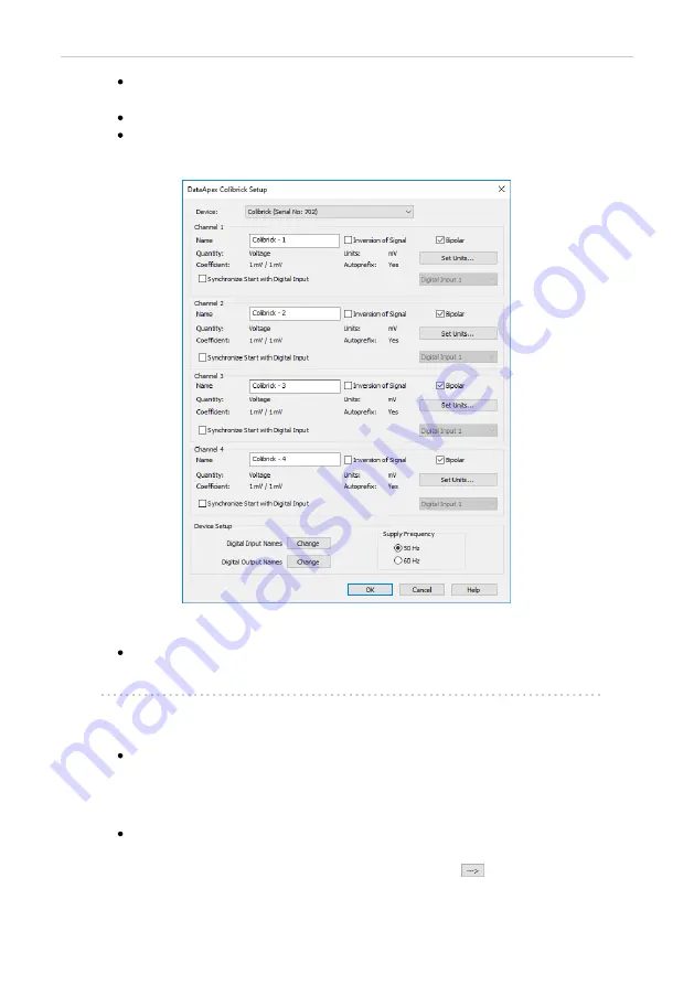
Fig 7: DataApex Colibrick Setup

Enter the detector names in

Name

fields for individual channels, set signal

units.

Note:

A detailed description of this dialog can be found in the chapter

"DataApex Colibrick Setup"

on pg

14

.

Press the

OK

button.

The

Colibrick

will appear in the

Setup Control Modules

list

of the

System Configuration

dialog.

Drag and drop the

Colibrick

icon from the

Setup Control Modules

list

on the left side of the

System Configuration

dialog to the chosen

Instrument

tab on the right side

(or use the

button

to do so).

- 10 -

Содержание COLIBRICK

Страница 1: ...K A D CONVERTER Clarity Hardware ENG Code Rev M149 80F Date 8 24 2020 Phone 420251013400 DataApex Ltd Fax 420251013401 Petrzilkova 2583 13 clarity dataapex com 15800Prague 5 www dataapex com The Czech Republic ...

Страница 2: ...ked with the icon Clarity DataApex and are trademarks of DataApex Ltd Microsoft and WindowsTM are trademarks of Microsoft Corporation DataApex reserves the right to make changes to manuals without prior notice Updated manuals can be downloaded from www dataapex com Author DR ...

Страница 3: ...are Configuration 21 4 3 Digital Inputs and Outputs 22 4 4 Device Monitor 23 5 Troubleshooting 24 5 1 Locate your problem 24 5 2 Problems with Colibrick 25 5 2 1 Colibrick s orange blue LED is blinking 26 5 2 2 How to check the proper installation of the Colibrick driver 27 5 2 3 Manual installation 29 5 2 3 1 Installation and re installation of the Colibrick driver 29 5 2 3 2 Reinstallation of dr...

Страница 4: ...dow WORK1 capitals indicates the name of the file and or directory ACTIVE capitalitalics marks the state of the station or its part The bold text is sometimes also used for important parts of the text and the name of the Clarity station Moreover some sections are written in format other than normal text These sections are formatted as follows Note Notifies the reader of relevant information Cautio...

Страница 5: ...matograph for the Clarity station Colibrick uses the USB communication channel and thus is directly powered from the PC The unit can be connected or disconnected anytime without the need to switch the computer off Fig 1 Colibrick A D Converter Brief technical overview 1 2 or 4 data acquisition channels completely independent and isolated from the USB ground 4 digital inputs with status indication ...

Страница 6: ... LED OFF the output status is Low logical 0 the relay contact is closed Note The above mentioned is valid if the device is used within the specifications stated in Colibrick A D Converter datasheet 1 2 Rear panel of the Colibrick device The rear panel contains the USB connector for connecting to the PC and the INT7 compatible connector for connecting to the chromatograph Fig 3 Rear panel of the Co...

Страница 7: ...time delays during which the converter fails to integrate the input signal No continuous servicing of the input analog switches which would otherwise cause errors offset noise Substantially smaller amounts of data entering the computer due to individual data items already representing partial integrals Parameters generally based on the INT9 A D cards 3 ...

Страница 8: ...table The PC must have a free USB slot Tab 1 Hardware and Software Compatibility Software Windows 10 8 1 7SP1 Clarity Clarity Lite Yes from 6 2 Yes from 4 0 3 Yes from 4 0 Both 32 and 64 bit version are supported Tab 2 Hardware and Software Compatibility with obsolete Windows OS Software Windows VistaSP2 32 and 64 bit XPSP3 Clarity Clarity Lite Yes from 4 0 to 7 2 Yes from 4 0 to 7 4 1 4 ...

Страница 9: ...ick device Install the Clarity software Caution Install Clarity before inputting any devices The drivers were copied to your computer and installed automatically during the installation of the Clarity software Note The Colibrick device is detected by its S N If you later replace one by another it is also necessary to reconfigure it in the Clarity System Configuration dialog 5 ...

Страница 10: ... shielding analog ground Starting marker cables The cables labeled IN1 to IN4 according to the number of channels are ended with a RCA connector Each starting cable has one cable with free leads red shielding digital ground for direct connection to the chromatograph or to a valve and one cable ended with a button for those cases where there is not a starting contact available and it is necessary t...

Страница 11: ... are sure that the chromatograph detector is equipped with a symmetrical output it is necessary to read through the instructions for the corresponding chromatograph Fig 5 Connecting Clarity to chromatograph Note Since INT7 converter all DataApex A D converters use the same standard INT7 Connector A description of the INT7 connector can be found in the chapter Tables and specifications on pg 41 7 ...

Страница 12: ...or easier modification of the wiring we supply a SV9 Terminal board p n SV9 with screw contacts Note This SV9 Terminal Board is not suitable for applications with small signals or with high electromagnetic interference This is because the SV9 Terminal Board uses leads and screw contacts that are not shielded 3 3 2 Connection of starting cables Starting input reacts to a change of the TTL logical l...

Страница 13: ...uration window in Clarity Lite Clarity Lite will use the first A D converter detected and assign a predefined configuration file for it Fig 6 System Configuration Start the Clarity station with the icon on the desktop Invoke the System Configuration dialog using the System Configuration command or via icon 9 ...

Страница 14: ...librick Setup Enter the detector names in Name fields for individual channels set signal units Note A detailed description of this dialog can be found in the chapter DataApex Colibrick Setup on pg 14 Press the OK button The Colibrick will appear in the Setup Control Modules list of the System Configuration dialog Drag and drop the Colibrick icon from the Setup Control Modules list on the left side...

Страница 15: ...e wires being used for the Start synchronization Note A detailed description and configuration of this functions can be found in the Reference guide and Getting Started manuals Note The configuration dialog of the Colibrick device DataApex Colibrick Setup can be displayed any time by double clicking on its icon or using the Setup button 11 ...

Страница 16: ...and drag it to another Instrument The Instrument to which the particular signal is connected is listed to the right and of the detector name in the Setup Control Modules section Fig 8 System Configuration multiple instruments Note Each independent Clarity Instrument must have separate Ext Start Dig Input and Ready Dig Output pins configured according to the actual wiring Note More Instruments more...

Страница 17: ...scribed in Fig 9 on pg 13 all signals from Colibrick 1 as well as all signals from Colibrick 2 are assigned to the Instrument 1 Where there are several converters assigned to the same Instrument it is necessary to select which converter will be used for Ext Start Dig Input and Ready Dig Output signals All added A D converters e g Colibrick must have their drivers properly installed There must be a...

Страница 18: ...Colibrick Setup The DataApex Colibrick Setup dialog is accessible from the System Configuration dialog The DataApex Colibrick Setup dialog sets the parameters of the Colibrick converter and since it depends on the type of connected signal it is not going to be changed often Fig 10 DataApex Colibrick Setup Device Shows the serial number of selected Colibrick If more than one Colibrick converter is ...

Страница 19: ...g the voltage measured by Colibrick to the units of the detector Such units will then be shown throughout Clarity instead of default mV Setting is specific for each Colibrick channel signal Fig 11 Detector Units Quantity Field for entering a name for the y axis in the graph of the measured signal Units Field for entering the unit symbol along with the prefix Coefficient Allows you to enter the coe...

Страница 20: ...lows to modify the naming of digital inputs and outputs and change the Mains Supply Frequency Suppression settings Digital Input Names Allows to change the names of digital inputs Fig 12 Digital Input Names Digital Output Names Allows to change the names of digital outputs These names will be used in the Digital Output Control dialog in the chapter Digital Inputs and Outputs on pg 22 Fig 13 Digita...

Страница 21: ...rts of the Americas the 60 Hz Mains frequency is usual while the rest of the world tends to use the 50 Hz Mains frequency pre set as default The 50 Hz frequency is common in countries using 230 V power supply while the 60 Hz is connected to the 117 V power supply 17 ...

Страница 22: ... Acquisition Fig 14 Method Setup Acquisition Colibrick Select Detector Selects the detector whose parameters are set If there is only one detector channel configured on the Clarity Instrument this control is not accessible Range Selects the input voltage range in mV The selected range corresponds to the maximum output voltage of the detector that the A D converter can still process In case the det...

Страница 23: ...frequency filter Higher sampling rate allows for the measurement of narrower peaks but it also means a larger amount of data which affects the size of the resulting chromatogram and the speed of its processing Sample rate sufficient for successful peak detection is about 20 samples per narrowest peak A higher sampling rate also increases the amount of noise and you need to set the Peak Width param...

Страница 24: ...nput will not influence the acquisition in progress Start Restart The external signal terminates the analysis in progress and at the same time starts a new one The first signal starts the analysis the second signal terminates it and at the same time starts a new one the so called continuous measurement Start Stop The external signal starts and stops an analysis The first signal starts the analysis...

Страница 25: ... V or to contacts opened in the relay 4 2 3 Hardware Configuration Fig 16 Hardware Configuration This dialog is invoked by pressing the Det Status button in the Method Setup Acquisition dialog Hardware Configuration dialog displays the connection and the details of the connected and selected Colibrick its firmware revision and serial number 21 ...

Страница 26: ...andard assignment of external Ext Start Dig Input and Ready Dig Output can be changed in the System Configuration dialog in the Fig 6 on pg 9 Note The assigned input and output is then automatically used in the ACTIVE sequence for synchronization with the autosampler or injection valve Digital Outputs of Colibrick dialog accessible from the Clarity window The Device Monitor window accessible from ...

Страница 27: ...ght switched off gray icon to logical zero LOW Descriptions Shows the description indicating the meaning of individual input The names of all digital inputs can be set in the DataApex Colibrick Setup dialog Output no Lists the numbers of individual outputs Current State Indicates the current status of the particular output which also works as relays Green light corresponds to logical one HIGH ligh...

Страница 28: ... The name of the window is visible in its header Note Names of individual Clarity Instruments appear in the header instead of the common term Instrument Tab 3 List of windows and dialogs Windows and Dialogs Clarity pg 33 Data Acquisition pg 36 pg 37 pg 38 pg 39 pg 40 Instrument pg 33 Method Setup pg 33 Sequence pg 33 Single Analysis pg 33 System Configuration pg 33 pg 36 pg 25 Tab 4 List of Error ...

Страница 29: ...ouble clicking on the device will not invoke the DataApex Colibrick Setup dialog l Clarity will issue an Error Message DataApex Colibrick SN XX Device not found when starting Clarity l The Data Acquisition icon in the Instrument window is not active this problem may also have another cause For more details see the chapter Data Acquisition non functional on pg 33 When one of the above mentioned pro...

Страница 30: ... by decrease in voltage on the Colibrick and that is why sometimes it cannot be added in the System Configuration Solution Check whether your Colibrick is connected to the PC via USB Hub If so we recommend to connect Colibrick directly to the PC this will ensure that the voltage will not suddenly decrease when other device is plugged in Another option is to try a different USB cable We have found ...

Страница 31: ...ok up the resulting list for the item Colibrick DataApex In the following image all drivers except the Colibrick driver are installed correctly Fig 19 Device Manager in Windows 7 Error status of the driver may be one of the following Status 1 The Chromatography Device Colibrick DataApex item does not appear Reason The driver has not been installed Solution Reinstall the driver manually as describe...

Страница 32: ... driver is disabled Solution Double click the item to invoke the General tab and activate the driver by clicking on the Enable this device button Status 4 The item does appear and there are no error symbols around it Reason A driver for a different type of Windows operating system was possibly installed thereby replacing the correct driver Solution Uninstall the incorrect driver and install the co...

Страница 33: ...e Colibrick driver Connect the Colibrick with a cable to a USB port on the computer Windows 10 8 1 and 7 do not install the driver automatically Use the Device Manager in the Control Panel Fig 20 Step 1 of Updating the driver l Right click on the Colibrick DataApex item and click the Update Driver Software item 29 ...

Страница 34: ...of the Installation Wizard Click the Browse my computer for driver software button Fig 22 Browse for driver dialog Browse for the Colibrick driver location In the example above the Clarity installation is located in the C CLARITY directory Then click Next 30 ...

Страница 35: ...on status and you can see also name of the driver which will be displayed in the Device Manager 5 2 3 2 Reinstallation of drivers using the System Restore Point Use the System Restore Point to uninstall the incorrect drivers Click on the Windows Start menu and type System Restore in the search field then click on the found item in In the System Restore dialog use the Choose a different restore poi...

Страница 36: ...ng Caution Any software or hardware that was installed after the moment of the selected restore point will be removed from your system Reinstall Clarity and then restart the PC Windows should now correctly identify and install the drivers 32 ...

Страница 37: ...ng Clarity Offline or Clarity DEMO version which does not enable the measurement of the chromatograms Fig 26 Clarity Offline and Clarity DEMO Solution Check whether there is a blue band with the text OFFLINE on the main Clarity window under the instrument icons or the title DEMO in the window header In case of the Clarity Offline station remove the HW key with the Offline license and insert key wi...

Страница 38: ...located detectors add them In the left hand side list Setup Control Modules select the correct detector and drag it to the corresponding instrument on the right If an appropriate detector is not in the left hand side list Setup Control Modules add it using the Add button and repeat the previous step Note More information on the System Configuration dialog can be found in the chapter Clarity Config...

Страница 39: ...y window using the System Configuration command and check the tab of the corresponding Instrument Instrument X If the symbol in the tab header is red this indicates the Instrument cannot be used for data acquisition b Check your serial number S N using the command Help About from the main Clarity window 35 ...

Страница 40: ...indow using the System Configuration command and check the tab of the corresponding Instrument Instrument X If it only has the detector signals from the DataApex DEMO detector it is necessary to reconfigure it You can find more information how to add a detector in the chapter Clarity Configuration on pg 9 b Make sure that you have installed a full version of Clarity If this is not the case inscrip...

Страница 41: ...s during the time of analysis Reason 1 The instability of the analysis conditions Solution Check the analysis conditions the detector settings the column and solvents for impurities Reason 2 Improper connection of the A D converter Solution If you are using the A D converter check whether the cable shielding is properly connected For more information see 3 3 on pg 7 37 ...

Страница 42: ... detector directly on the device b If you are using direct control with digital acquisition not using any A D converter decrease the sensitivity in the Method Acquisition dialog accessible from the Instrument window Reason 2 A low range set for the A D converter Solution Set a higher range in the Method Acquisition dialog accessible from the Instrument window Reason 3 An improper connection of the...

Страница 43: ...etector directly on the device b If you are using direct control with digital acquisition not using any A D converter increase the sensitivity in the Method Acquisition dialog accessible from the Instrument window Reason 2 A high range set for the A D converter Solution Set a lower range in the Method Acquisition dialog accessible from the Instrument window Reason 3 An improper connection of the A...

Страница 44: ... on pg 7 Reason 2 The analytical conditions problem Solution Check the system for wrong injection or wrong conditions temperature FID flame etc Reason 3 The chromatograph problem Solution If a voltmeter is available connect it to the chromatograph and check voltage changes during an analysis with a real sample Reason 4 The A D converter failure Solution You can perform a simple test Connect an AA ...

Страница 45: ... the 1st channel AGND Ground of the analog channels IN1 Digital input of the 1st channel Used as an External Start marker of the 1st channel OUT1 1st Digital output Digital outputs are controlled by Event Table ACTIVE sequence Device Monitor dialog and Digital outputs of DataApex Colibrick dialog DGND Ground of the digital inputs and outputs OUT1S1 OUT1S2 Digital outputs 1st relay contact Contact ...

Страница 46: ...ed as relay contacts OUT 1 4 S1 OUT 1 4 S2 The maximum permissible switching current is 0 5 ADC max contact resistance 150 mΩ max voltage 100 V The relay is on state closed at level LOW of a relevant digital output Digital Inputs The Colibrick A D converter contains four digital TTL inputs IN1 to IN4 To suppress contact bouncing the digital inputs are equipped with monostable toggles that prolong ...

Страница 47: ...Colibrick A D Converter 6 Tables and specifications 6 3 Colibrick CE conformity declaration Fig 36 CE Conformity declaration Colibrick 43 ...

Страница 48: ... Crystal inaccuracy 50 ppm may cause shift of the signal in milliseconds during 1 hour analysis or in seconds during a week long analysis Digital inputs 4 TTL 5 V Digital outputs 8 TTL 5 V maximum current load 20 mA maximum total current load for all outputs 100 mA 4 of them also as relay contacts normally open i e contact closure max current 0 5 ADC max voltage 100 VDC max switching power 10 VA m...

Отзывы: