


19
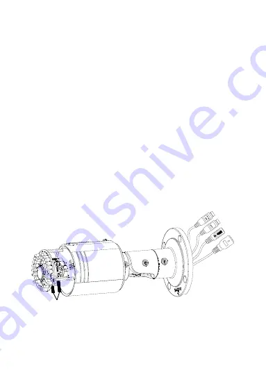
Zoom and focus adjusting
You can use the zoom lever and focus lever to adjust the zoom
value and focus value.
To adjust zoom and focus:
1.
Disassemble the camera.
2.
View the camera image using the monitor.
3.
Loosen the zoom lever and move the lever between
T (Tele) and W (Wide) to obtain the appropriate angle of
view.
4.
Tighten the zoom lever.
5.
Loosen the focus lever and move the screw between
F (Far) and N (Near) to obtain the optimum focus.
6.
Tighten the focus lever.
7.
Assemble the camera.
Levers
Содержание CV-M3B10-ODI
Страница 2: ......
Страница 4: ......
Страница 6: ...ii...
Страница 12: ...6 Wiring Wire your bullet camera as shown in Figure 3 Figure 3 Wiring...
Страница 18: ...12 1 1 1 1 2 2 2 2 1 Screw Hole for Bracket 2 Screw Hole for Mounting Base Cable Hole Screw Hole...
Страница 24: ...18 Pan Tilt Rotation Lock screw 1 Lock screw 2 Lock screw 3...
Страница 32: ...26 6 Click Next 7 Click Finish...
Страница 39: ......
Страница 40: ......


