background image

8

DX 18..27

D

GB

8

Installation (Fortsetzung)

Installation (continuation)

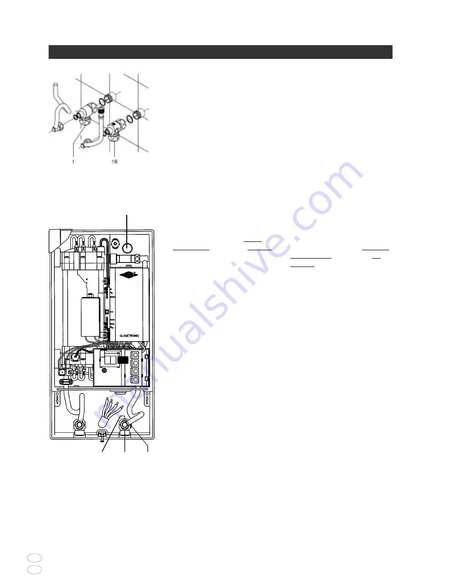
Installing connection pieces

1. As shown in the illustration, screw the

cold water connection piece (18) with
the union nut and the 1/2" seal onto
the cold water connection.

2. Screw the hot water connection piece

(1) with the union nut and the 1/2"
seal onto the hot water connection.

Installing the appliance

1. To open the appliance hood, undo the

hood securing screw.

• When replacing an appliance, the

electrical power supply cable may
already be connected in the upper part
of the appliance. In such a case, but
only then, press against the prepared
breaking point (S) with a blunt
implement (e.g. screwdriver).

• Slit the grommet (19) to match the

cable size. The opening in the grommet
should be slightly smaller than the 
cross-section of the cable in order to
ensure optimum protection against
water. Fit the grommet into the
opening.

• Strip the cable roughly 6 cm above the

point where it emerges from the wall.
Hold the prepared appliance so that you
can route the cable into the grommet
with the other hand.

2. Place the appliance on the heater

carrier (9) so that the threaded rod of
the wall holder fits in the hole on the
appliance. If necessary, slight
corrections are possible by carefully
bending the outlet pipe. However, it
must be possible to screw on the
water connection pipes of the
appliance without applying force.

Anschlussstücke installieren

1. Schrauben Sie gemäß Abbildung das

Kaltwasseranschlussstück (18) mit
Überwurfmutter und der 1/2“-
Dichtung an den Kaltwasseranschluss.

2. Schrauben Sie das Warmwasser-

anschlussstück (1) mit  Überwurf-
mutter und der 1/2“- Dichtung an 
den Warmwasseranschluss.

Gerät montieren

1. Zum Öffnen des Gehäuses die

Haubenschraube lösen.

• Im Austauschfall kann es vorkommen,

daß die Elektrozuleitung im oberen
Gerätebereich vorhanden ist. Nur dann
öffnen Sie die Sollbruchstelle (S) an 
der Prägung durch kräftigen Druck 
mit einem stumpfen Werkzeug 
(z.B. Schraubendreher).

• Schneiden Sie die Durchführungstülle

(19) entsprechend dem Zuleitungs-
querschnitt auf. Dabei soll die Öffnung
in der Tülle etwas kleiner als der
Querschnitt des Kabels sein, um einen
optimalen Schutz gegen Wasser zu
erzielen. Passen Sie die Tülle in den
Durchbruch ein.

• Manteln Sie das Elektrokabel ungefähr

60 mm über dem Wandaustritt ab.
Nehmen Sie das vorbereitete Gerät so in
die Hand, daß Sie mit der anderen
Hand das Kabel in die Gummitülle
führen können. 

2. Setzen Sie das Gerät auf den Wand-

halter (9), so daß die Gewindestange
des Wandhalters in das vorgesehene
Loch des Gerätes paßt. Durch
vorsichtiges Biegen des Auslaufrohres
lassen sich gegebenenfalls kleine
Korrekturen vornehmen. Die Wasser-
anschlussleitungen des Gerätes
müssen sich jedoch ohne
Gewaltanwendung anschrauben
lassen.

S

18c

18

18a

Содержание DX 18

Страница 1: ...ektroinstallation erste Inbetriebnahme sowie die Wartung dieses Ger tes d rfen nur durch einen zugelassenen Fachmann entsprechend dieser Anleitung vorgenommen werden Mounting water and electrical inst...

Страница 2: ...safety thermal cut out 82100 3 Zwischenwand intermediate panel 82090 2 Auslaufrohr hot water pipe 82131 1 Warmwasseranschlussst ck hot water connection 82085 20 1 2 Einschraubnippel screw in nipple 8...

Страница 3: ...the components whilst in transit It is made from environmentally friendly re usable corrugated cardboard The plastic bags are made of recyclable polythene PE The plastic components of the appliance ar...

Страница 4: ...ie Kaltwasserzuleitung Lassen Sie die St rung nur vom Werks kundendienst oder einem anerkannten Fachhandwerksbetrieb beheben Installation initial operation and maintenance of this appliance must only...

Страница 5: ...spec water spez Wasserwiderstand 1 100 cm resistance 15 C spez elektr Leitf higkeit 90 9 mS m Electrical conductivity Einlauftemperatur 50 C Inlet temperature Elektroanschluss2 3 PE 400V AC Electrica...

Страница 6: ...Kunstoffrohre d rfen nur verwendet The following regulations must be observed EC or national regulations Germany VDE 0100 and EN 806 2 The regulations of the local power and water supply utilities Th...

Страница 7: ...sich bis zu 30 mm durch die mitgelieferten Distanzh lsen ausgleichen Die Distanzh lsen werden zwischen Wand und Wandhalter 9 montiert Je nach Versatz sind die kurzen oder langen Befestigungsschrauben...

Страница 8: ...However it must be possible to screw on the water connection pipes of the appliance without applying force Anschlussst cke installieren 1 Schrauben Sie gem Abbildung das Kaltwasseranschlussst ck 18 m...

Страница 9: ...en Ende der Einschraubnippel 20 zu verschrauben Die Warm und Kaltwasseranschlussst cke sind dann mit den 3 8 Dichtungen an die 3 8 berwurfmutter des Ger tes und Auslaufrohres zu verschrauben Bei Direk...

Страница 10: ...Betriebsart 1 zu w hlen und die Funktion des Lastabwurfrelais bei kleiner Ger teleistung 35 Grad Sollwert und geringer Wassermenge zu pr fen Kommt es zu einem Flackern des Abwurfrelais so muss die Be...

Страница 11: ...lussschraube 5 Setzen Sie die Abdeckhaube auf das Ger t und drehen Sie die Befestigungsschraube ein 10 Anschluss nur durch den Fachmann Electrical connection only by a specialist Standard electrical c...

Страница 12: ...zu gew hrleisten 5 Setzen Sie die Abdeckhaube auf das Ger t und drehen Sie die Befestigungsschraube ein Electrical connection from above only up to 10 mm2 1 Secure the wiring set 21 to the terminal ho...

Страница 13: ...tarting it up again 2 Switch on the power supply to the appliance The digital display on the appliance must light up 3 Open the hot water tap The appliance starts working 4 Check the function of the i...

Страница 14: ...ng ausgestattet Es gibt zwei M glichkeiten eine Temperaturbegrenzung einzustellen 1 38 C Verbr hungsschutz Gleichzeitig Programmtaste und dr cken AUS OF MAX 38 C As soon as you open the hot water tap...

Страница 15: ...rreichen kann Sie k nnen die volle Leistungsabgabe nutzen um zum Beispiel die Badewanne schnell zu f llen Mischen Sie dann kaltes Wasser entsprechend zu 2 Individual temperature limit only possible if...

Страница 16: ...ventil bis keine Luft mehr aus der Leitung austritt und der Durchlauferhitzer luftfrei ist 4 Erst dann d rfen Sie die Stromzufuhr zum Durchlauferhitzer wieder einschalten und den Perlator wieder einsc...

Страница 17: ...stritt 8 Setzen Sie die Ger tehaube auf Danach schalten Sie die Spannung an den Haussicherungen wieder ein Hinweis Bei einer Aufputz Installation ist die Funktion des Absperrventils nicht gegeben Main...

Страница 18: ...L neburg Tel 04131 89 01 40 Fax 04131 89 01 41 E Mail service clage de 16 Garantiebedingungen Diese Garantiebedingungen gelten nur f r den Kauf und Einsatz unserer Ger te in der Bundesrepublik Deutsc...

Страница 19: ...rvice clage de These guarantee terms shall be governed solely after purchase and use of our appliances in the Federal Republic of Germany Abroad the corresponding guarantee terms are based on the cont...

Страница 20: ...on 04131 89 01 0 Telefax 04131 83 200 E Mail clage clage de Internet www clage de nderungen vorbehalten Gedruckt auf Umweltschutzpapier These instructions are subject to alteration notice Printed an e...

Страница 21: ......

Отзывы: