


INSTALLATION / OPERATION / MAINTENANCE
49-01
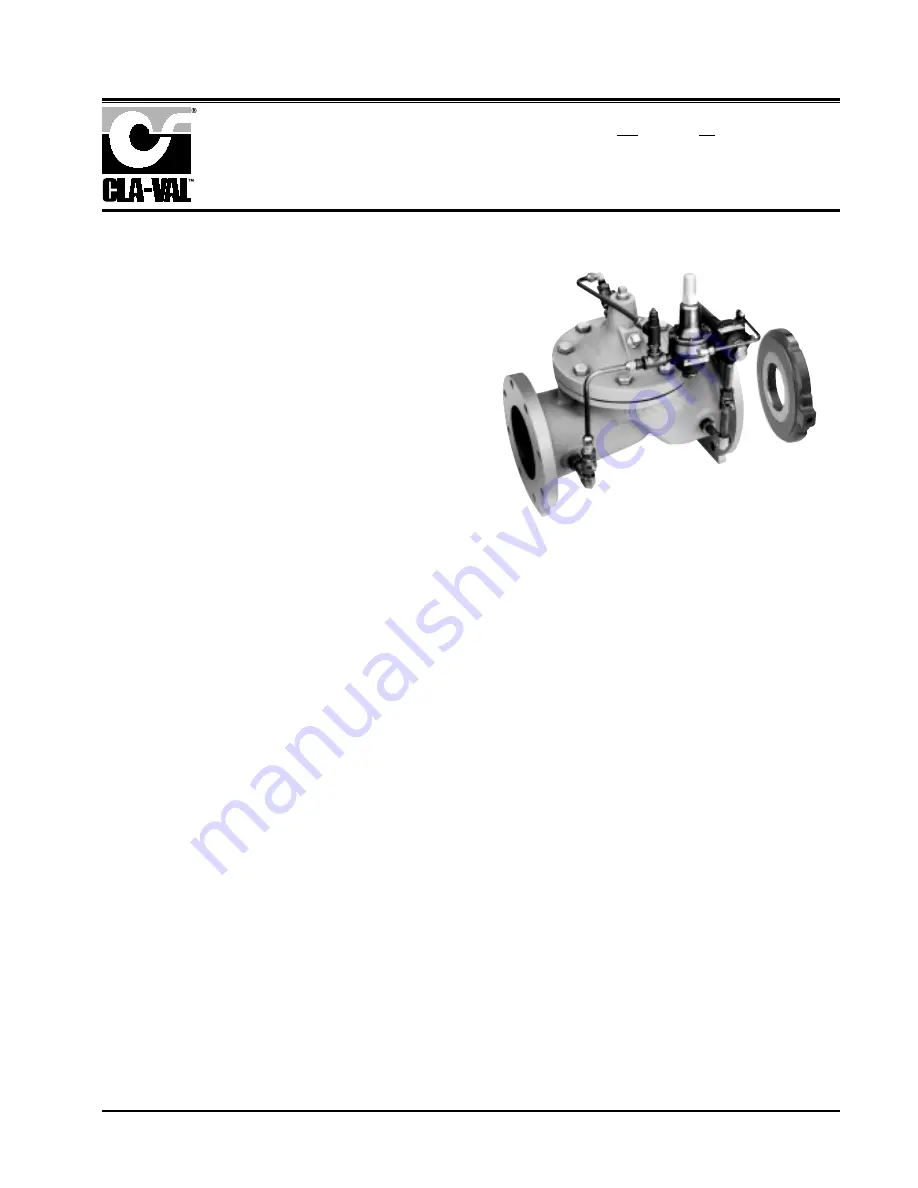
MODEL
Rate of Flow Controller & Pressure Reducing Valve
INTRODUCTION
This manual titled the 49-01 Series Combination Rate of Flow
Controller and Pressure Reducing Valve contains information
for installation, operation and maintenance of the valve and
control system.
The Cla-Val 49-01 is an automatic valve designed to reduce a
higher inlet pressure to a steady lower downstream pressure
regardless of changing flow rate and/or varying inlet pressure,
as long as the flow rate is below a preset maximum. The auto-
matic valve also prevents excessive flow by limiting flow to a
preselected maximum rate.
The Cla-Val 49-01 is a single seated, hydraulically operated,
pilot controlled diaphragm type globe or angle valve. The pilot
system includes a direct acting, spring loaded, pressure reducing
pilot (CRA) and a rate of flow differential control (CDHS-18).
INSTALLATION
1. Allow sufficient room around the valve to make adjustments
and for disassembly.
2. It is recommended that gate or line block valves be installed
upstream and downstream of the Cla-Val valve assembly to
facilitate isolating the valve for preventive maintenance.
NOTE:
BEFORE THE VALVE IS INSTALLED, PIPE LINES
SHOULD BE FLUSHED OF ALL CHIPS, SCALE AND FOREIGN
MATTER.
3. Place valve in line with flow through the valve in the direction
indicated on the inlet plate or by flow arrows. Check all fittings
and hardware for proper makeup and that no apparent damage
is evident. Be sure main valve cover nuts/bolts are tight.
Pressure in some applications can be very high so be thorough
in checking and inspecting for proper installation and makeup.
4. For best control, it is recommended that the orifice plate
restriction be installed 1 to 5 pipe diameters downstream of the
main valve. The flow arrows should be pointing to the downstream
side of the system.
5. A sensing line, supplied by other than Cla-Val, must be con-
nected between the orifice plate holder and the Differential
Control. See dotted lines on schematic drawing.
6. Cla-Val Valves operate with maximum efficiency when
mounted in horizontal piping with the cover UP; however, other
positions are acceptable. Due to size and weight of cover and
internal components of six inch valves and larger, installation
with the cover up is advisable. This makes periodic inspection
of internal parts readily accessible.
OPERATION AND START-UP
1. Operation of the Cla-Val 49-01 Series Valve is fully automatic
once the flow rate and reduced pressure settings have been
made. Modulation in the main valve is brought about by the
action of the pressure reducing and differential pilot controls.
Throttling of either of these controls in response to changes in
the flow rate or downstream pressure produces a change in the
flow rate through the control system. This, in turn, causes
changes in the main valve cover chamber pressure.
It is the constant variations of main valve cover chamber pressure
which forces the main valve to seek new throttling positions in
response to slight changes in the flow rate or downstream pressure.
The controls are so arranged that the reducing control is in
command of the main valve only when the flow rate is below the
setting of the differential control. The valve, therefore, holds a
constant delivery pressure. If, however, the flow rate reaches
the preset maximum the differential control takes command and
holds the flow rate at the desired maximum. Under these conditions
of increased demand the downstream pressure falls below the
normal reduced pressure.
2. Prior to pressurizing the valve assembly, make sure the nec-
essary gauges are installed, to measure required pressure and
flow, as designated by the system engineer. A Cla-Val X101
Valve Position Indicator may be installed in the center cover
port to provide a visual indication of the stem position during
startup adjustment.
CAUTION:
During startup and test procedures a large volume
of water may be discharged downstream. Check that the down-
stream venting is adequate to prevent damage to personnel
and equipment.
3. With the downstream block valve closed, slowly open
upstream block valve. If isolation valves are installed, as shown
on the schematic, open these valves slowly.
Distributed By: M&M Control Service, Inc.
http://www.mmcontrol.com/claval-index.php
800-876-0036 847-356-0566
Содержание 49-01/649-01
Страница 17: ...Distributed By M M Control Service Inc http www mmcontrol com claval index php 800 876 0036 847 356 0566...
Страница 18: ...Distributed By M M Control Service Inc http www mmcontrol com claval index php 800 876 0036 847 356 0566...
Страница 19: ...Distributed By M M Control Service Inc http www mmcontrol com claval index php 800 876 0036 847 356 0566...
Страница 22: ...Distributed By M M Control Service Inc http www mmcontrol com claval index php 800 876 0036 847 356 0566...
Страница 23: ...Distributed By M M Control Service Inc http www mmcontrol com claval index php 800 876 0036 847 356 0566...
Страница 26: ...Distributed By M M Control Service Inc http www mmcontrol com claval index php 800 876 0036 847 356 0566...
Страница 29: ...Distributed By M M Control Service Inc http www mmcontrol com claval index php 800 876 0036 847 356 0566...


