


DESCRIPTION
The CRA Pressure Reducing Control automatically reduces a higher inlet
pressure to a lower outlet pressure. It is a direct acting, spring loaded,
diaphragm type valve that operates hydraulically or pneumatically and is
designed to sense pressure from a remote point. It may be used as a self-
contained valve or as a pilot control for a Cla-Val Co. main valve. It will
hold a constant downstream pressure at the remote sensing point within
very close pressure limits.
OPERATION
The CRA Pressure Reducing Control is normally held open by the force
of the compression spring above the diaphragm; delivery pressure acts on
the underside of the diaphragm. Flow through the valve responds to
changes in pressure at the the sensing point.
INSTALLATION
The CRA Pressure Reducing Control may be installed in any position.
There is one inlet port and two outlets, for either straight or angle instal-
lation. The second outlet port can be used for a gauge connection. A flow
arrow is marked on the body casting.
ADJUSTMENT PROCEDURE
The CRA Pressure Reducing Control can be adjusted to provide a deliv-
ery pressure range as specified on the nameplate.
Pressure adjustment is made by turning the adjustment screw to vary the
spring pressure on the diaphragm. The greater the compression on the
spring the higher the pressure setting.
1. Turn the adjustment screw in (clockwise) to increase delivery
pressure.
2. Turn the adjustment screw out (counter-clockwise) to decrease
the delivery pressure. When pressure adjustment is completed,
tighten jam nut on adjustment screw and replace protective cap.
Flow rates are not critical during pressure setting. The approximate min-
imum flow rates given in the table are for the main valve on which the CRA
is installed.
Valve Size
1 1/4"-3"
4"-8"
10"-16"
Minimum Flow GPM
15-30
50-200
300-650
MAINTENANCE
Disassembly
To disassemble follow the sequence of the item numbers assigned to
parts in the sectional illustration.
Reassembly
Reassembly is the reverse of disassembly. Caution must be taken to
avoid having the yoke (17) drag on the inlet nozzle of the body (18).
Follow this procedure:
1. Place yoke (17) in body and screw the disc retainer assembly
(16) until it bottoms.
2. Install gasket (14) and spring (19) for 2-30 psi range onto plug
(13) and screw into body. Disc retainer must enter guide hole in
plug as it is assembled. Screw the plug in by hand. Use wrench
to tighten only.
3. Place gasket (25) and powertrol body (21) on yoke extension
(17). Refer to sectional view for proper reassembly of (21) onto
body (18).
4. Place lower diaphragm washer (24), "o" ring (22), diaphragm
(12), upper diaphragm washer (11), and belleville washer (20) on
yoke extension (17). Screw on diaphragm nut (10) finger tight.
5. Place two machine screws (4) through (21) (25) and screw into
body (18). Do not include the diaphragm (12) in this operation.
This holds parts aligned for next step, and allows the diaphragm
to move and be properly located during tightening of nut (10).
6. Hold the diaphragm so that screw holes in the diaphragm (12)
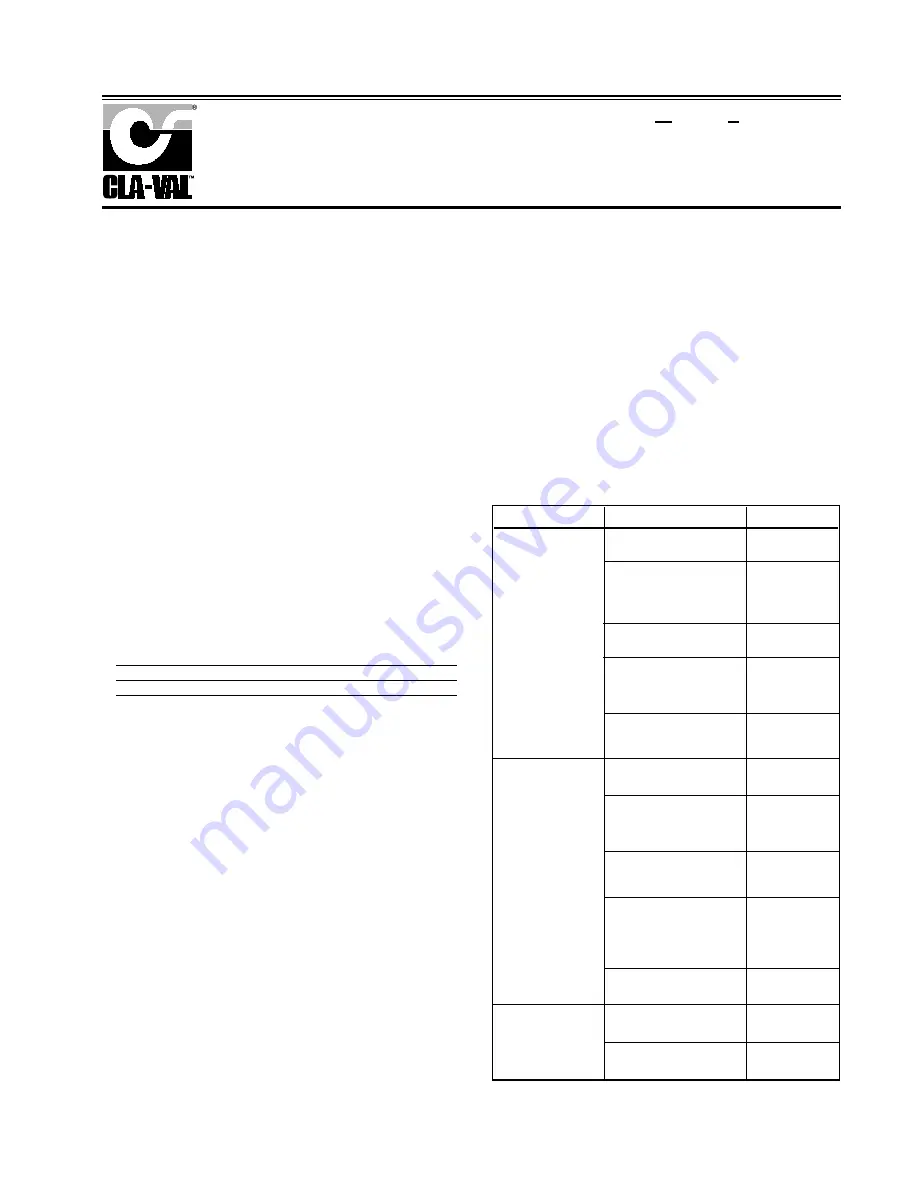
SYMPTOM
PROBABLE CAUSE
REMEDY
Fails to open when
pressure lowers
No spring compression
Tighten adjusting
screw
Mineral buildup on yoke
extension (17)
Disassemble and
clean part,
Replace "O" rings
(22) and (23).
Damaged spring
Disassemble and
replace.
Spring guide (8) is not in
place
Disassemble and
place guide (8) on
top of spring (9).
Yoke dragging on inlet
nozzle
Disassembled
and reassemble
use procedure.
Fails to close when
delivery pressure rises
Spring compressed
Back off adjusting
screw
Mineral deposit on yoke
extension (17)
Disassemble and
clean part.
Replace "o" rings
(22) and (23).
Mechanical obstruction
Disassemble and
remove obstruc-
tion
Worn disc
Disassemble,
remove and
replace disc
retainer assem-
bly. (16)
Yoke dragging on inlet
nozzle
Refer to para-
graph 6
Damaged diaphragm (12)
Disassemble and
replace
Loose diaphragm nut (10)
Remove cover
and tighten nut
REMOTE SENSING TYPE
CRA
Leakage from cover
vent hole
MODEL
INSTALLATION / OPERATION / MAINTENANCE
N-CRA (R-9/00)
and powertrol body (21) align. Tighten diaphragm nut (10) with a wrench.
At the final tightening release the diaphragm and permit it to rotate
approximately 5° to 10°. The diaphragm holes should now be properly
aligned with the body holes.
To check for proper alignment proceed as follows:
Rotate diaphragm clockwise and counterclockwise as far as possible.
Diaphragm screw holes should rotate equal distance on either side of
powertrol body screw holes ±1/8".
Repeat assembly procedure until diaphragm and yoke are properly
aligned. There must be no contact between yoke and body nozzle during
its normal opening and closing movement. To simulate this movement
hold powertrol body and diaphragm holes aligned. Move yoke to open
and closed positions. There must be no evidence of contact or dragging.
7. Remove machine screws per step 5.
8. Install spring (9) with spring guide (8) on top of spring.
9. Install cover (5) using eight machine screws (4).
10. Replace adjusting screw (2) and nut (3), then cap (1).
Pressure Reducing Control
Distributed By: M&M Control Service, INC.
Phone: 800-876-0036 Fax: 847-356-0747 Email: [email protected]
Distributed By: M&M Control Service, Inc.
http://www.mmcontrol.com/claval-index.php
800-876-0036 847-356-0566
Содержание 49-01/649-01
Страница 17: ...Distributed By M M Control Service Inc http www mmcontrol com claval index php 800 876 0036 847 356 0566...
Страница 18: ...Distributed By M M Control Service Inc http www mmcontrol com claval index php 800 876 0036 847 356 0566...
Страница 19: ...Distributed By M M Control Service Inc http www mmcontrol com claval index php 800 876 0036 847 356 0566...
Страница 22: ...Distributed By M M Control Service Inc http www mmcontrol com claval index php 800 876 0036 847 356 0566...
Страница 23: ...Distributed By M M Control Service Inc http www mmcontrol com claval index php 800 876 0036 847 356 0566...
Страница 26: ...Distributed By M M Control Service Inc http www mmcontrol com claval index php 800 876 0036 847 356 0566...
Страница 29: ...Distributed By M M Control Service Inc http www mmcontrol com claval index php 800 876 0036 847 356 0566...


