1) First, be sure hardware set-up and wiring to actuator is completed. Connect laptop computer to actuator using special USB
cable. Be sure computer is on and actuator is powered. Check that Actuator LED is steady green.
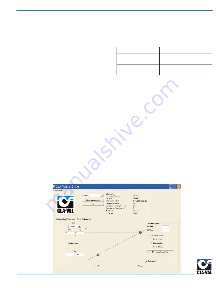
2) Start the CLA-VAL actuator software by clicking on “e-Drive” desktop icon. After program opens, the Configuration mode
tab will be displayed as default. System values are displayed for pressure or flow settings. Click on setting range values
and enter new system pressure or flow values for 4 mA and 20 mA settings. Engineering Units can be changed to PSI to
Bar or Kpa, GPM to L/S and inches to meters.
3) Click on Read parameters button to display Calibration tab window with system values and display of General Information.
The date of last calibration, the average and total working time since first power up, the number of starts, the serial
number, the Firmware version, and the maximum and minimum recorded temperature inside the actuator are displayed.
Also, Calibration tab window will open without clicking on Read parameters button.
4) Open Configuration tab window to change
Rotation Speed
. Change speed by adjusting actuator on and off times to equal
slower or faster net rotation speed. Factory default setting of one second on and five seconds off is a net rotation speed of
about one rpm. Longer off times will slow down the actuator. Maximum ratio of 1/1 is a net speed of six rpm. Click on
download to actuator button to make this parameter change without affecting other settings.
Slower rotation speeds are recommended.
5) Open Calibration tab mode to set (
Loss-of-Signal mode
). Select one of three options for actuator action upon
loss of 4 - 20 mA command input signal. If actuator has power it will do one of the following:
Go to 4 mA:
Actuator will decrease pilot setting to 4 mA position.
Last position:
Actuator will stay in last position.
Highly recommended
Go to 20 mA:
Actuator will increase pilot setting to 20 mA position.
Click on download to actuator button to make this parameter change.
In the event of loss of power, actuator will stay in last position and valve will control at last set-point.
Starting Actuator Software
32 Series Actuator and Software Set-up
Change 130VC-2 Actuator configuration from factory default settings,
by using free download software from website (www.cla-val.com). To
set up a communication link with 130VC-2 Actuator, first install
software and cable driver and then special USB communications
cable in laptop computer. After installing driver and communication
cable, the actuator must be powered for link to work. Follow hard-
ware set-up and wiring diagram instructions. Your computer must
be on before powering the actuator.
Hardware set-up steps must be completed before program will
communicate and change 130VC-2 factory default settings. Until
wiring and power connections are made to the actuator, the soft-
ware program can be opened, but new parameters can not be cre-
ated or stored or sent to actuator. Changes to parameters must be
done "live" and while control valve is operating.
Install Special Communications CABLE
On 130VC-2 Actuator, remove small protective plastic cover and
attach Special Communications Cable to connector using short
orange wire and attach other cable end to computer USB port.
When finished running software and downloading settings to actu-
ator, remove cable and
reinstall small protective plastic cover.
Troubleshooting Actuator Software Set-up
Problem
Check
The software is not opening
Are you using Windows XP or
Windows 2000?
No connection to actuator
Check if the USB driver is working
Page 3
Fig. 1


