background image

10

operation:

Welding:

Maintenance:

hand held:

Machine:

prior to commencing welding, the following preparations should be made to ensure 
optimum performance of the system.

With the shield gas flowing, initiate an arc between the tungsten electrode and 
the workpiece. When the desired weld pool has formed, depress the switch on the 
torch to start the wire feeding. adjust the Wire speed and, if in pulse mode adjust 
the drive time and dwell time to produce the desired bead.

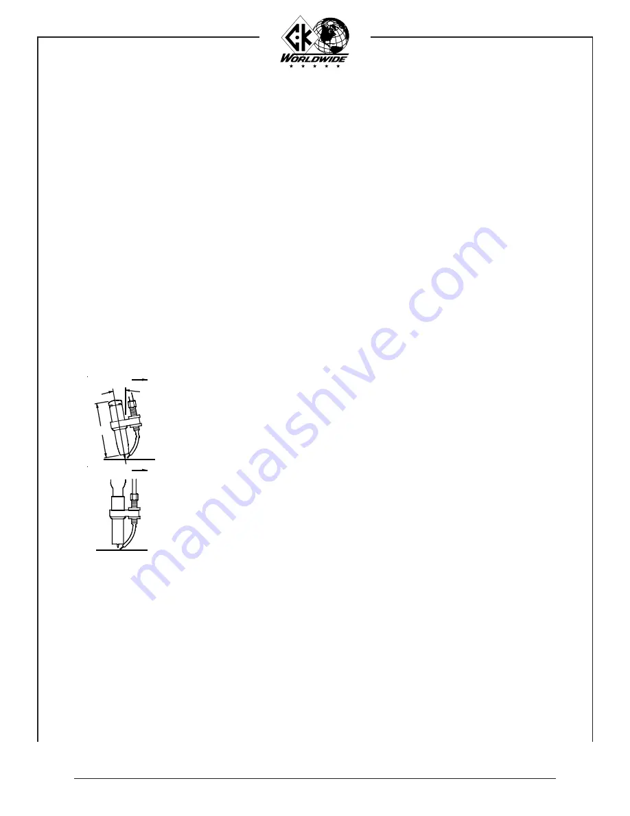
the recommended torch angle for hand held welding is 15° from perpendicular. 
the filler wire is fed into the leading edge of the molten pool.

the recommended torch angle for machine mounting welding is perpendicular. the 
filler wire is fed into the leading edge of the molten pool.

1.  Make sure that the pieces of metal to be welded are free of grease, dirt, paint, 

and scale. Use a wire brush to remove dirt and scale. Use a stainless steel wire 
brush on stainless or aluminum. paint must be completely removed to bare metal. 
failure to clean the metal properly will result in porous and contaminated welds. 

2.  check that the system has been properly installed per the installation instructions. 

3.  check the control cable and weld cables for proper connection. Make sure the 

ground clamp is firmly attached to a cleaned area on the piece to be welded. 

4.  prepare the torch for welding. check the gas supply and adjust the flowmeter for 

the recommended flow rate. check the water circulator for proper operation. 

5.  set the controls on the power source and the cold Wire tig feed Unit.

1.  Blow foreign matter from the feed cable with compressed air before loading a new 

spool of welding wire. 

2.  replace the wire guide tube if it has been arced, bent, or is badly worn. 

3.  Wire drive motor brushes should be inspected at regular intervals and replaced if 

worked to a 1/4” (6.4mm) length.

Whenever a brush is removed for inspection, be sure it is put back in the 
same position. it must not be turned around in the brush holder. excessive 
arcing and loss of power will result if it is put back incorrectly.

note:

Direction of Travel

15°

3-3/4"

Direction of Travel

Содержание WF5

Страница 1: ...ical diagram functionsofcontrols parts lists Wf5 feed Unit left side Wf5 feed Unit right side cWh1812 hand torch cWh2312 hand torch cWhtl312 hand torch parts lists cWh3512 hand torch cWM2312 Machine t...

Страница 2: ...nd gases can be hazardous to your health 1 Keep your head out of welding fumes 2 Use adequate ventilation in the work area to keep fumes and gases from your breathing zone and the general work area 3...

Страница 3: ...way from heat sources such as furnaces wet conditions such as water puddles oil or grease corrosive atmospheres and inclement weather 5 Keep all safety devices guards panels and covers in position and...

Страница 4: ...rranty gives you specific legal rights and you may have other rights which may vary from state to state The CK Cold Wire TIG System consists of 1 The Cold Wire TIG Wire Feed Unit and 2 The Cold Wire T...

Страница 5: ...electrode negative half cycle and the good cleaning action of reverse polarity electrode positive half cycle continuous high frequency is necessary to reestablish the arc which breaks between each ha...

Страница 6: ...ontinuously variable continuously variable continuously variable 180 amp ACHF or DCSP 300 amp ACHF or DCSP 350 amp ACHF or DCSP 400 amp ACHF or DCSP Water 12 1 2 ft 3 81m 8 ft 2 44m 10 ft 3 05m 300 am...

Страница 7: ...urce ground terminal to the work or fixture The ground cable should be adequate size and no longer than the torch leads 3 Attach the torch water in and gas supply hoses to their respective connections...

Страница 8: ...ed roll to be sure it is on the correct side for the filler wire being used See page 21 for drive roll sizes Unlatch and raise the pressure roll arm Thread the wire through the inlet guide to the driv...

Страница 9: ...l result in deformed wire and needless overload of the drive motor iMportant Warning note Warning 8 the wire feed rolls and spool brake are properly adjusted at the factory prior to delivery as compon...

Страница 10: ...e completely removed to bare metal Failure to clean the metal properly will result in porous and contaminated welds 2 Check that the system has been properly installed per the installation instruction...

Страница 11: ...n pressure roll re thread wire 7 Plug in feeder to a 115V AC wall outlet 8 Replace feed cable 9 Align inlet and outlet guides with drive roll 10 Adjust spool brake 11 Replace wire guide tube Erratic w...

Страница 12: ...m CWT023 CWGH Curved CWGHS Straight S CWG023H S 030 8mm CWT030 CWG030H S 035 9mm CWT035 CWG035H S 045 1 1mm CWT045 CWG045H S 1 16 1 6mm N A CWG116H S NOTE A bracket extension is needed for complete in...

Страница 13: ...elay 12v dc relay logic circUit card Motor 2 ohM 50 Watt delay sW 2 delay p 1 retract sW 3 retract p 2 1 1 11 12 10 3 2 12 k1 k2 13 14 8 9 3 6 12v 11 13 10 9 4 4 c1 c2 c3 5 5 6 7 7 field 8 trigger Mot...

Страница 14: ...lse continuous selector switch controls mode of operation continuous or pulse wire feed mode f circuit Breaker 5 amp breaker provides overload protection for control circuit g remote amphenol Wf5 acti...

Страница 15: ...15 81 11 0051 79 400 0169 87 400 0167 87 001 1107 79 4 400 0166 87 400 0181 92 400 0003 81 DESCRIPTION Power Cord Cabinet Strap Spool Hub Right Door 12V DC Relay Handle Motor Drive Circuit Card Fuse H...

Страница 16: ...n Bolt tension nut pressure spring tension Bolt Washer tension Bolt roll pin pressure roll pressure roll screw pressure roll Bushing pressure roll retainer nut pressure roll spacer pressure roll arm s...

Страница 17: ...2A7 2CB332 2C332GS CWKN See Page 12 CWF CWN1 CWFC or CWFCN 2312TF 12 5 ft 3 8m 2AN 3HF 2WN 3HF 2PN 23PF2 23PF1 2312PC 12 5 ft 3 8m 212AH 12 5 ft 3 8m 212WH 12 5 ft 3 8m 01 0032 CK180 80THS 8CB332 8C5...

Страница 18: ...D TORCH CWKN CWKN CWHS 3C332GS See Page 12 3A7 3CB332 TL300 WGB 3 300R 300L 6S5 3035 SWB SW4 3036 SS1 6S5 CWHTL3HA 230HE including 6S5 s and SS1 SC BULK 01 0127 512PC 12 5 ft 3 8m 2PN 51PF2 51PF1 2WN...

Страница 19: ...ional options on head consumables Note See Page 25 for additional options on head consumables CWKN CWKN CWHS 3C332GS WGB 3 CWFC or CWFCN CWFC116 or CWFCN116 CWF CWN1 312WH 12 5 ft 3 8m 2WN 3HF 3H BULK...

Страница 20: ...CWKN CWKN CWMT400 118 024 2 required CWKN M512PC 1 12 5 ft 3 8m MTPCFA 5PCH BULK 5PCW BULK 312WH 12 5 ft 3 8m 2WN 3HF 3H BULK 3AG12LD CWTS 2PN 51F 1184 51F CWFC or CWFCN CWFC116 or CWFCN116 CWF CWN1 2...

Страница 21: ...PARTS RECOMMENDEDSPAREPARTSLIST Feed cables 1 Wire guides 2 Adjusting nuts 2 Heat shields 1 Cups 10 Collets 10 Collet bodies 6 Backcaps 2 Wire guide bracket extensions 1 See page 12 See page 12 See to...

Страница 22: ...08 2A5 13N09 2A6 13N10 2A7 13N11 2A8 13N12 2A10 13N13 STANDARD 2CB20 13N25 2CB40 13N26 2CB116 13N27 2CB332 13N28 2CB418 13N29 STANDARD 2C20 13N20 2C40 13N21 2C116 13N22 2C332 13N23 2C418 13N24 STANDAR...

Страница 23: ...None 7C332 None 7C418 None 7C532 None GASLENS CWHSGL None ALUMINA 3AG4 54N18 3AG5 54N17 3AG6 54N16 3AG7 54N15 3AG8 54N14 3AG11 54N19 GASLENS 3GL20 45V29 3GL40 45V24 3GL116 45V25 3GL332 45V26 3GL418 45...

Страница 24: ...STANDARD 2GHS None CERAMIC 2C4 13N14 2C5 13N15 2C6 13N16 2C7 13N17 2C8 13N18 2C10 13N19 WEDGE 2C040GS None 2C116GS None 2C332GS None 2C418GS None REVERSE 6C20 None 6C40 None 6C116 None 6C332 None 6C4...

Страница 25: ...one 7C40 None 7C116 None 7C332 None 7C418 None 7C532 None GASLENS CWHSGL None ALUMINA 3AG4 54N18 3AG5 54N17 3AG6 54N16 3AG7 54N15 3AG8 54N14 3AG11 54N19 GASLENS 3GL20 45V29 3GL40 45V24 3GL116 45V25 3G...

Страница 26: ...COLLET STANDARD 4C20 10N21S 4C40 10N22S 4C116 10N23S 4C332 10N24S 4C418 10N25S 4C532 None BACKCAP LONG AL35 2304 0143 MEDIUM AM35 2304 0144 SHORT AS35 2304 0143 ALUMINA 3AG4 54N18 3AG5 54N17 3AG6 54N1...

Страница 27: ...LOWING CK TIG TORCHMODEL CWMT500 3 SERIES CWMT512 ALUMINA 3AG4 54N18 3AG5 54N17 3AG6 54N16 3AG7 54N15 3AG8 54N14 3AG11 54N19 GASLENS 3GL20 45V29 3GL40 45V24 3GL116 45V25 3GL332 45V26 3GL418 45V27 3GL5...

Страница 28: ...or use on automated or robotic applications Runs cooler than 2 Thoriated with longer life Low to medium amperage range ELECTRODE DIAMETER CUP SIZE WELDING CURRENT AMPS TUNGSTEN TYPE ARGON FLOW FERROUS...

Страница 29: ...rally as the included angle increases penetration increases and bead width decreases Use a medium 60 grit or finer aluminum oxide wheel taper length 2 3 X dia flat 1 4 to 1 2 X dia typical tip geometr...

Страница 30: ...4 6 4mm 3 16 4 8mm 10 ARGON 35 17 15 260 10 256mm FILLET Magnesium was one of the first metals to be welded commercially by TIG Magnesium alloys are in three groups they are 1 aluminum zinc magnesium...

Страница 31: ...s then 0 30 carbon and less than 1 2 5cm thick generally do not require preheat An exception to this allowance is welding on highly restrained joints These joints should be preheated 50 to 100 F 10 to...

Страница 32: ...ck Worldwide inc 3501 c st n e auburn Wa 98002 phone 800 426 0877 fax 800 327 5038 www ckWorldWide com form 5701...

Отзывы: