CITROËN ID 19 Скачать руководство пользователя страница 116

Содержание ID 19

Страница 1: ......

Страница 2: ......

Страница 3: ...he figure 0 indicates the adjustments The figures 1 4 7 indicate the replacement of units removal and refitting The figures 2 5 8 indicate the stripping down and assembling The figures 3 6 9 indicate...

Страница 4: ...the strictest cleanliness see Op ID 00 WORK ON THE BODY AND UNDERBODY REPAIR To preserve the vehicle s roadholding and braking qualities it is essential to locate correctly components to which mechani...

Страница 5: ...iming gear 120 Suspension 133 Feed system Manifolds 141 Carburettor and controls 142 Air filter 171 Petrol pump 173 Piping 174 Petrol tank 175 Exhaust system 180 Ignition system Distributor 211 Igniti...

Страница 6: ...433 REAR SUSPENSION 434 Piping 435 Manual height control 437 STEERING 440 Steering wheel 441 Steering rack 442 Steering relays 443 BRAKES 451 Hydraulic control master cylinder pedal gear piping 453 M...

Страница 7: ...nd float of the crankshaft 36 47 Fitting the timing gear 37 47 Fitting the oil pump on the engine 38 47 Crankcase ID 111 1 Work on the crankcase 49 Replacement of the Bump 1 50 Replace of the sealing...

Страница 8: ...low running 11 86 ID 142 3 Overhauling a Solex 34 PBIC carburettor 1 87 Controls ID 142 4 Work on the carburettor controls 89 Replacement of an accelerator control cable 1 89 Replacement of an acceler...

Страница 9: ...g a Ducellier distributor 25 116 ID 211 4 Replacement of an advance control 1 118 Oil system ID 220 0 Checking the oil pressure on the car 1 119 ID 220 1 Work on the oil circulating system Replacement...

Страница 10: ...140 GEARBOX ID 330 1 Replacement of a gearbox 1 141 Oil level 33 145 ID 330 2 Preparing a gearbox for stripping down 1 146 ID 330 3 Overhauling a gearbox 1 147 Preparing the differential 24 154 Prepar...

Страница 11: ...the balls of the selector bell crank lever 22 176 Replacement of a selector support 34 177 TRANSMISSION ID 372 1 Work on the transmission 179 Replacement of a driveshaft or a pivot 1 179 Replacement o...

Страница 12: ...Mock 1 203 FRONT AXLE ID 410 1 Replacement of a front half axle 1 204 Positioning the half axle on the sidemember 12 205 Pre adjustment of the heights 19 206 Adjustment of the heights see Op ID 433 0...

Страница 13: ...umulator see Op ID 391 0 Front suspension ID 433 1 Work on the front suspension 237 Replacement of a suspension sphere or a damper 1 237 Replacement of a height corrector 7 238 Replacement of a suspen...

Страница 14: ...60 Adjustment of the lateral position of the steering assembly 1 260 Adjustment of the alignment of the steering 5 260 Adjustment of the track 7 261 Adjustment 0 the steering lock 10 261 ID 441 1 Repl...

Страница 15: ...er cylinder 1 293 Replacement of a pedal gear 12 295 ID 453 3 Work on the Hydraulic Brake Control Overhauling a master cylinder On cars produced since February 1958 1 296 On cars produced before Febru...

Страница 16: ...amo 315 Overhauling a Ducellier 7158 A dynamo 1 315 Overhauling a Paris Rh ne G11 R91 dynamo 25 318 Starter motor ID 533 1 Replacement of a starter motor 1 321 ID 533 3 Overhauling a starter motor 322...

Страница 17: ...djustment of rear engine supports 1699 r 1 25 Spanner for adjustment of rear engine supports 1700 T 1 25 Spanner for adjustment of rear engine supports 1982 T 1 61 Spanner for hydraulic pipe union 9 m...

Страница 18: ...er for plugs closing crankshaft oil ways MR 3462 70 4 12 Punched plate for fitting cylinder barrel joints MR 4134 4 40 Mandrel for centring clutch disc 1712 T 2 13 Piston ring guide 1656 T 1 18 Stand...

Страница 19: ...ing in housing 1771 T 1 57 Spring compressor for locking lever spring 1792 T 2 57 Spanner for spindle caps MR 3691 80 3 58 Fixture for alignment of pulleys 1683 T 1 56 Mandrel for positioning fork con...

Страница 20: ...uge for pre adjustment of the heights 2307 T 1 65 Vice support for half axle MR 3053 120 2 64 Extractor for axle arm 1864 T 1 64 Spanner for anti roll bar ball joint MR 3691 40 3 66 Vice support for p...

Страница 21: ...rs 2483 T I 54 Spanner for the clamp of the corrector control rod 1677 T see gearbox 1 61 Spanner for hydraulic pipe unions 9 mm opening 2219 T see pressure reserve 61 Spanner for hydraulic pipe union...

Страница 22: ...xture for checking concentricity of rear brake linings 2115 T 2 103 Pincers for rear brake shoe return springs 2210 T 2 105 Assembly for rivetting rear brake cam spindles MR 3354 40 6 ADJUSTMENTS 58 F...

Страница 23: ...ystem should be perfectly clean The strictest precautions must be observed during work on the car and for the storage of the fluid and spare parts 1 Storage Pipes units and spare parts must be protect...

Страница 24: ...1 for the union on the accumulator control valve 1 cap D 433 82 for the accumulator pressure regulator disconnected c Distribution block see flg 3 3 plugs D 391 63 d Height corrector see fig 4 3 plugs...

Страница 25: ...the bore VERY IMPORTANT Make sure that the end of the pipe enters the small bore at b 3 Screw the connecting nut by hand On some units the axis of the bores is oblique relatively to the face of the b...

Страница 26: ...pipe 49 Adjust the ignition advance see OP ID 211 0 Check the level of the engine oil 7 pints 4 litres of SAE 20 oil 50 With the engine idhng and the car on the ground fill the radiator Bleed the brak...

Страница 27: ...k the position of the steering gear in the bearing at b Disconnect the steering levers 1 from the relay spindles Remove the set screw 2 from the steering pinion Remove the bearing caps and withdraw th...

Страница 28: ...emove the nuts from the engine fixing studs on the rear brackets 23 mm spanner 23 Remove the front wheels Disconnect the flexible couplings Bibax from the gearbox driving plates 12 mm socket wrench wi...

Страница 29: ...acken the nuts securing the steel plate support to the car body Offer the engine gearbox assembly up to the car Tighten the upper screws securing the crossmember to the sidemembers plain washer and sp...

Страница 30: ...on the panel to the fully retarded position and then move it forward two notches Make sure that the spring moves the distributor into the fully retarded position Tighten the cable fixing screw Operat...

Страница 31: ...90 and 93 e f1 Position the steering pinion so that the reference mark made when dismantling corresponds paint mark opposite the slot in the flexible coupling at a Engage the steering pinion in the fl...

Страница 32: ...fixing collar of the pipe to the bracket and tighten the nuts plain and spring washers Mount battery support insert distance piece between battery support and cross support of gearbox Tighten the fix...

Страница 33: ...ont brake cooling ducts the air deflector plate the front wings the support bar the front wheels tighten the wheel screws to 108 to 144 ft lbs 15 to 20 m kg Replace the spare wheel Remove the bonnet r...

Страница 34: ...nect the flexible fuel feed pipe and vacuum pipe spanner 1647 T see Pl 16 fig 3 e Remove fuel pump f Remove pipe connecting pump and control valve spanner 2220 T see Pl 61 fig 3 and seal the pipe and...

Страница 35: ...3 cl Connect the flexible petrol feed pipe to the carburettor d Connect the vacuum pipe to the distributor and the carburettor 12 mm box spanner 12 mm box spanner 12 mm box spanner 14 mm box spanner 1...

Страница 36: ...anner 2431 T see Pl 61 fig 1 Fit the starter nose contact screws tighten moderately Tighten locknuts STRIPPING AND ASSEMBLING to replace the gearbox Remove the expansion chamber support Store carefull...

Страница 37: ...ghten the screws securing the clutch housing spanner 1677 T see Pl 65 fig 4 and spanner 2431 T see Pl 72 fig 1 f Fit the clutch control lever with its shouldered washer Connect the control rod to the...

Страница 38: ...ing cap screws is 36 ft llbs 5 m kg admissible clearance 0 06 mm max between the crank shaft and the connecting rod bearings Note the reference marks made when dismantling the bearings and caps Fittin...

Страница 39: ...ite cylinder being on the point of balance 1st cylinder with 4th cylinder valves balanced 3rd cylinder zvith the 2nd cylinder valves balanced 4th cylinder with 1st cylinder valves balanced 2nd cylinde...

Страница 40: ...entre and rear half bearings which are of the same size so that they are not reversed on assembling c Remove the crankshaft connecting rod and piston assembly Remove the crankshaft bearing thrust ring...

Страница 41: ...inion 17 ex ractor 1964 T see P1 10 fig 4 t Do not use the dowel insert a cylindrical pressure pad 12 mm dia x 40 mm long between the extractor screw and the pump shaft Release the shaft assembly 18 a...

Страница 42: ...f the seat must be between 0 9 and 1 5 mm Use the following grinding wheels to obtain these dimensions Inlet valve seat For the valve seat face 120 biconical wheel 1662 T For top clearance 150 biconic...

Страница 43: ...d then dip into engine oil Replace filter To refit oil pump see Pl 10 a Fit the bush 27 into the support tube 22 in a press b Insert the idler pinion spindle 23 in a press mount the idler pinion 16 ma...

Страница 44: ...ur Above this temperature the heat treat ment of the ring will be modified Make sure that the flywheel is perfectly clean and fit the ring quickly ensuring that it is kept perfectly level Grind the be...

Страница 45: ...ightly provided that the following maximum clearances are adhered to on the bearings 0 06 mm on the connecting rods 0 06 mm Using a micrometer measure the diameter of the bearing faces they should be...

Страница 46: ...verse the position of the cap on the rod Tighten the screws to 36 ft lbs 5 m kg socket 1624 T see Pl 16 fig 6 This torque is essential NOTE The bearings are slightly narrower than the cap and the big...

Страница 47: ...en with the lubricating holes directed downwards and towards the valve place on it the following starting from the front 1 long screw 3 fitted with bearing cap 33 for securing the shaft 1 washer 37 1...

Страница 48: ...he studs Tighten the nuts d Insert short cylinder head fixing screws Screw up without tightening h Tighten the screws in the order indicated see Pl 7 tightening on first occasion to 21 75 ft lbs 3 m k...

Страница 49: ...k punch mark on one tooth of the camshaft pinion and through the gap between the teeth which were marked with a punch see Pl 15 fig 2 One should also use the setting gauge 1680 T see Pl 15 fig 2 This...

Страница 50: ...bs 5 m kg torsion spanner 2471 T see Pl 7 fig 2 NO lock washers under the screw heads To couple the clutch to the flywheel a Make sure that the clutch disc bearing faces on the flywheel and the clutch...

Страница 51: ...ing side arms spring washer under screw head Fit the cylinder head lubricating tube using a double copper gasket when securing to the cylinder head and 2 copper gaskets when securing it to the crankca...

Страница 52: ...endjoat which should be 0 03 to 0 09 mm REPLACEMENT OF THE SUMP To remove Remove the engine gearbox assembly see Op ID 100 1 paragraphs 1 to 25 Leave the engine gearbox assembly suspended from the pu...

Страница 53: ...nner 1645 T see Pl 16 fig 3 12 13 Remove the flexible pipe and water pipe assembly left hand side Disconnect the leads from the sparking plugs Remove the rubber and bakelite caps from the sparking plu...

Страница 54: ...ections 9 and 10 b Remove the fixing screws from the bearings Mark the direction of assembly of the centre bearing cap remove the bearing caps together with their bearings and mark the latter c Raise...

Страница 55: ...hten the nut 39 spanner 1667 T see P1 15 fig l Push the crankshaft towards the bearing on timing gear side using a lever or a wedge located between a crankshaft throw and the crankcase Measure the cle...

Страница 56: ...over and place it on stand 2497 T see Pl 19 Insert sealing cups and the rubber joints on the sparking plugs tubes Fit cylinder head cover s king the gasket to the cover with Hermetic Tighten the fixi...

Страница 57: ...ot mislay the sealing joints 2 for the sparking plug tubes Adjust the clearance of the valve rockers to 0 008 0 20 mm for the inlet valves 0 010 0 25 mm for the exhaust valves Adjust the valves of one...

Страница 58: ...5 T see Pl 16 fig 3 I Disconnect the intake and delivery hoses from the water pump 12 17 mm box spanners Remove the radiator tie bar Remove the fan Remove the dynamo tie rod and release the belt 9 Dis...

Страница 59: ...g dowels are on the cylinder block Place the cylinder head in position Be careful of the lubrication pipes and the petrol outlet pipe Slightly raise the rockershafts and fit the push rods the longest...

Страница 60: ...he radiator tie bar plain and spring washers Secure the flexible air pipe on the radiator tie bar Fit a Ligarex collar pliers 2483 T see Pl 17 fig 2 Pliers 2483 T 25 Connect the intake and delivery ho...

Страница 61: ...er shaft assembly Remove fixing screws 3 the clamps 33 rhe washers 37 the springs 45 and the rocker arms 34 and 35 Drive out the plugs from the rocker shaft by means of a pin punch passing through the...

Страница 62: ...d 3 The lowest part of the end of the guide must be directed towards the centre of the combustion chamber If necessary make a reference mark at this point with a little paint before fitting the guide...

Страница 63: ...Length 37 mm under load of 53 lbs f 3 lbs 24 2 f 1 350 kg Length 28 5 mm under load of 115 lbs f 6 lbs 52 f 2 800 kg b Inner springs Length 24 5 mm under load of 11 5 lbs f 75 lbs 5 250 f 0 300 kg Le...

Страница 64: ...ew complete with cap 1 washer 1 right hand rocker 1 spring 1 washer 1 long screw complete with cap Fit the brackets and the inlet rocker shaft assemblies on the cylinder head Fit the water pump cover...

Страница 65: ...P1 7 Adjust the valve rocker clearances Inlet 0 008 0 20 mm Exhaust 0 010 0 25 mm see Op ID 112 O Replacement of an exhaust valve rocker assembly Place the shaft in position with the lubrication holes...

Страница 66: ...fixing screws 43 of the cylinder head right side Remove the 4th exhaust rocker shaft the first five screws fixing the inlet rocker shaft and their caps 33 the washer and the spring of the first inlet...

Страница 67: ...ocker shaft Tighten the fixing screws inserting the caps Adjust the valve rocker clearances to 0 008 0 20 mm for the inlet valve rockers and to 0 10 0 25 mm for the exhaust valve rockers see Op ID 112...

Страница 68: ...nd a washer 37 2nd and 4th cylinders place on the shaft starting from the front a washer 37 the rocker 36 and a spring 29 Place the shaft in position on its bracket with the lubrication holes towards...

Страница 69: ...it totters in position collar MR 4244 T spring compressor 1614 T see Pl 17 fig 4 Remove the cylinder head fixing screws 43 right hand side and the inlet rocker assembly and cylinder head fixing screws...

Страница 70: ...cylinder head cover see paragraphs 15 to 17 this operation Remove the rubber gaskets 2 and the cups 1 from the sparking plug tubes Remove the rocker assembly Strip the shaft remove the washer 37 the r...

Страница 71: ...aged on the spherical end ofthe adjusting screw t Adjust the valve rocker clearance to 0 010 0 25 mm see Op ID 112 O Fit the cylinder head cover see paragraphs 23 to 26 this operation TO CLEAN A CYLIN...

Страница 72: ...hten the screws fixing the rear thrust flange to 7 2 ft lbs I m kg lockwashers Insert a brass washer under the head of each of the three stews projecting inside the timing case Tighten the cylinder he...

Страница 73: ...rence marks to be aligned Then fit the chain on the two pinions To fit the timingchain and gear assembly a Move the two end pistons to the T D C b Without displacing the pinions put the chain and gear...

Страница 74: ...ckets 15 Remove the rocker push rods Remove the fixing screw from the union of the cylinder head lubrication pipe Disconnect the flexible fuel feed pipe from the carburettor Remove the retaining brack...

Страница 75: ...il with the crimped edges towards the cylinder block Fit the cylinder head Replace the rocker push rods first oiling the sockets Fit the exhaust rocker assembly brackets the bracket assemblies rocker...

Страница 76: ...he dynamo cl Connect the flexible petrol pipe to the carburettor Adjust the height of the front left hand brake unit turn the adjusting nuts of the front support tie bar until the plates project sligh...

Страница 77: ...Pl 1 and 3 Drain the cooling system radiator and cylinder block Retain the water which contains anti freeze Remove the air filter and tube assembly 2 17 mm box spanners Remove the cylinder head see Op...

Страница 78: ...00 T see Pl 25 fig 2 Slacken the locknut 12 using spanner 1699 T see Pl 25 fig 1 Tighten or slacken the adjusting nut until the fibre and rubber washer 9 rotates freely without play spanner 1700 T Tig...

Страница 79: ...embly Insert the threaded shaft fitted with parts comprising the lower assembly f rom underneath the car into thef7exible mounting and tighten the top nut of the engine support arm until1 the distance...

Страница 80: ...bar Disconnect the water pump delivery hose from the radiator and disconnect the hose between the radiator and the steel pipe from the steel pipe Remove the screws securing radiator to lower front cr...

Страница 81: ...rubber blocks are in position on the supports on the crossmember and place the radiator in position Couple the hoses and tighten the clips Place the distance piece between the exhaust downpipe bracke...

Страница 82: ...icle jacking bracket 2505 T see Pl 111 Left hand side disconnect the distributor return spring Right hand side removethe exhaust manifold screen Remove the upper fixing nut 1 from the arm 2 Pass a cov...

Страница 83: ...anners 35 Left hand side hook on the distributor return spring Right hand side fit the exhaust manifold screen Tighten the fixing screws plain washers under heads 12 mm box spanner 36 Lower the car to...

Страница 84: ...w REPAIRING A FLEXIBLE ENGINE MOUNTING cars delivered until July 195 9 23 mm box spanner 14 17 mm spanners and box spanners 12 mm box spanner Dismantling see Pl 25 Remove the spindle B the rubber and...

Страница 85: ...l 42 and support the engine on a chainblock Remove the screws fixing the rear arm 2 and withdraw the arm Refitting see Pl 25 Place the rear arm 2 in position and tighten the fixing screws spring washe...

Страница 86: ...H ave the locknut 5 firmly held from beneath the car by an assistant spanner 1700 T see fig 3 Tighten the lower fixing nut 3 of the arm 2 until the measurement a mentioned in paragraph 25 is obtained...

Страница 87: ...e fibre joint Remove the cover plate of the inlet manifold _ REFITTING To assemble the inlet manifold Place the cover plate in position and insert a gasket smeared with Hermetic Fit the fixing sleeve...

Страница 88: ...to 11 Connect the choke control Make sure that the choke opens and closes correctly Connect the union for the vacuum pipe and the flexible petrol inlet pipe to the carburettor Connect the tube betwee...

Страница 89: ...rew and remove the choke tube 15 Remove the accelerating pump 16 from the carburettor body Remove the pump lever pin 17 remove the spring 18 and washer 19 Disconnect the accelerator pump secured by fo...

Страница 90: ...or 12 insert a paper joint and tighten the screw Place the emulsion tube 14 in position and screw up the air corrector jet 13 Fit the float 10 in position complete with its spindle 11 Fit the cover pa...

Страница 91: ...welded on the body if not set the pedal rod in the area d REPLACEMENT OF AN ACCELERATOR CABLE Removal see Pl 27 Disconnect the cable 1 from the control cam 2 Remove the stop 3 for the outer casing the...

Страница 92: ...ease on the pedal bracket Place the locknut 12 against the pedal bracket and insert the screw 13 into the locknut 15 16 Place the pedal in position and screw the threaded spindle 13 into the pedal bea...

Страница 93: ...the facia panel fit the spring washer and the fixing nut for the outer casing ferrule on the choke control Insert the cable and cable outer casing through the rubber ring on the bulkhead Tighten the...

Страница 94: ...r Disconnect the tube from the filter 2 Remove the nuts fixing the air filter Remove the air filter 12 17 mm box spanners REFITTING 3 Place the air filter in position Connect the tube between the filt...

Страница 95: ...oints are glued in position If not glue them again with glue EC 847 sold by the Societe MINNESOTA de FRANCE 135 boulevard Serrurier Paris 19e Telephone No BOL 71 79 and BOT 42 80 NOTE For efficient op...

Страница 96: ...lace the rear cover and pipe assembly 6 in the body of the air filter 7 Fit the front cover 3 complete with felt gasket 4 Arrange the rear fixing bracket 10 in relation to the front bracket 11 Tighten...

Страница 97: ...om the pump Remove the fixing nuts and remove the pump Remove the gasket f TO FIT Position the cork gasket and the pump on the pump bearing face on the crankcase Tighten the fixing nuts springwashers...

Страница 98: ...16 and sealing cap 17 f NOTE The inlet and outlet valve seats are incorporated in the pump cover If the valves do not function properly the pump must be replaced Clean the components ASSEMBLY see Pl 3...

Страница 99: ...sure of l to 4 p s i 100 to 300 g cm2 through the rubber petrol hose At the beginning there may be a few bubbles due to movement of the diaphragms Maintain the pressure for a short period If bubbles o...

Страница 100: ...right hand sill and from the front closing panel of the right hand sidemember Disengage the pipe from the sidemember by pulling it towards the front REFITTING Close the front and rear openings in the...

Страница 101: ...n the rubber sleeve using talc to facilitate the work Couple the sleeve to the petrol pump Place the feed pipe in the straps on the front closing panel of the sidemember the front crossmember under th...

Страница 102: ...nd rear suspension cylinder by pass return No DS 391 149 T union securing return rubber hose to petrol tank No DS 391 146 NOTE The unions are sold complete with 60 mm pipe on each outlet Likewise obta...

Страница 103: ...ed pipe from the tank Block the orifices of the pipe and the tank Remove the right hand rear wing Remove the right hand rear side protection panel Carefully clean the area where work is to be done rou...

Страница 104: ...fig 2 Fit the side protection panel Fit the wing Pliers 2483 T 8 mm spanner and box spanner 14 mm box spanner 15 Connect the rear end of the flexible hose of the petrol pump feed pipe at about 370 mm...

Страница 105: ...the pipe Disconnect the flexible hose between the filler pipe and the tank from the pipe Remove the piping from the front Refitting Place the filler pipe in position and engage in the flexible connect...

Страница 106: ...Fit a Ligarex clip pliers 2483 T see Pl 17 fig 2 Connect the rear end of the air pipe to the flexible connection hose of the filler pipe of the tank Fit a Ligarex clip pliers 2483 T see Pl 17 fig 2 F...

Страница 107: ...nk unit on the petrol tank 47 48 49 Replace the rear seat and squab REPLACEMENT OF A PETROL GAUGE TANK UNIT Removal Refitting Introduce the tank unit float into the tank and place the tank unit in pos...

Страница 108: ...ove the gaskets Refitting 8 Place the manifold in position and insert the copper and asbestos gaskets 9 10 11 12 13 Fit the manifold screen retaining clips The longest upper clip is fitted at the fron...

Страница 109: ...he nuts of the fixing screws of the half collar assemblies securing the pipe to the silencer and to the manifold Remove the front pipe or the expansion chamber Refitting Place the expansion chamber or...

Страница 110: ...s of the half collars of the silencer outlet pipes remove the rubber stops the screws the rubber bands and the half collars Refitting Assembling the silencer Fit the fixing half collars of the silence...

Страница 111: ...he rubber band fixing screws under the body and remove the plates During this operation support the rear end of the exhaust pipes Remove the fixing screws of the flanges securing the exhaust outlet pi...

Страница 112: ...flanges of the exhaust outlet pipes and silencer outlet pipes Put the fixing collars of the exhaust outlet pipes in place and tighten the nuts of the fixing screws of the half collars and of the rear...

Страница 113: ...the distributor place the control lever so that the stop cut into the casing retaining plate is in the centre of the control lever groove retard position and tighten the set screw of the distributor...

Страница 114: ...s have been undone apply an A C current of 110 v 50 cycles between the positive terminal and the earth inserting a lamp in series in the circuit Apply this voltage for 1 minute if the lamp lights insu...

Страница 115: ...e the latter is partially masked by by the dynamo Turn the engine slowly in its own direction of rotation until the rod engages in the recess in the flywheel The engine is then at the firing point at...

Страница 116: ...washers Unhook the springs 15 remove the rollers 17 remove the cam 18 and remove the friction washer Remove the flat ring 19 R emove spade terminal 20 terminal 21 contact 22 contact support 23 and th...

Страница 117: ...iction washer on spindle Place the cam 18 in position with the small side of the dog towards the operator the groove in the cam will be on the right Fit the rollers 17 the smaller end upwards Fit the...

Страница 118: ...age the contact support 6 To dismantle the contact support plate a Remove the connecting clip 13 remove the fibre washer 14 and the movable contact 15 together with the primary wire 16 b Remove the ro...

Страница 119: ...p 36 Place the contact support assembly 6 in the body of the distributor Fit the spring 12 and tighten the screw 11 fixing the spring and the contact support 6 insert the terminal of the earth lead an...

Страница 120: ...complete with washer in position washer shoulder towards the front Connect the handle to the control serrated washer between the control and the facia panel Tighten the hollow fixing screw of the con...

Страница 121: ...hicle Start the engine and let it run in order to bring the oil to a temperature of about 600 C Switch off the engine Remove the cylinder head lubrication screw Connect the pressure gauge feed pipe us...

Страница 122: ...k Drain the oil from the engine Remove the sump avoid damaging the gaskets Remove the distributor Unscrew the pipe union from the oil pump Unscrew the pipe union on the cylinder block and rotate the p...

Страница 123: ...such replacement gaskets so that they are flush with the bearing caps using a sharp knife Carefully clean the mating faces of the cylinder block and the sump Cut the replacement gaskets to make them f...

Страница 124: ...d measured at g 0 3 mm The thickness of the adjusting washers of the pulley must be reduced by 0 3 x 3 t 0 45 x 2 0 90 t 0 90 1 80 mm 2nd case When the rod bears on g If the clearance d measured at I...

Страница 125: ...ashers will have to be increased by 0 40 0 225 x 4 0 70 mm 3rd case If the clearance d measured at h is less than 0 225 0 05 mm the thickness of the adjusting washers will have to be reduced by 4 time...

Страница 126: ...t faces of the cover 48 and the pump with Hermetic Stick the joint on the cover Offer up the pump Tighten the nuts and fixing screws 9 10 11 12 Connect the rubber pipes to the pump Tighten the clips f...

Страница 127: ...e retaining rings 8 Remove cup 9 and the packing 10 Remove the pump bearing 11 The bearing can be released by hand but use a drift if necessary Remove bushing 12 extractor 2291 T see P1 37 fig 4 Clean...

Страница 128: ...on a stand stand MR 3676 180 see Pl 37 fig 1 Place the bearing 11 in position in the pump body using a tube Fit the nut 6 locking the bearing 11 p s anner 1646 T see P1 37 fig 2 Put in position the pu...

Страница 129: ...he dynamo fixing screws Connect the flexible air hose to the radiator tie bar Fit a Ligarex clip pliers 2483 T see Pl REPLACEMENT OF A DYNAMO AND WATER PUMP DRIVING PULLEY Removal see Pl 49 Disconnect...

Страница 130: ...tray the spare wheel and the left hand front wing 12 14 mm box spanners 19 20 21 22 23 24 25 Fit the steering assembly see Op ID 100 1 paragraph 42 Remove the steering assembly see Op ID 100 1 paragr...

Страница 131: ...sition and remove the fixing nut l the locking washer 2 and the washer 3 Withdraw the pulley the key 4 and the adjusting washer 5 Withdraw the belt from the rear of the dynamo tie rod i Refitting see...

Страница 132: ...ve the distance pieces between the exhaust pipe bracket and the radiator retaining strap Remove the radiator _ Refitting Make sure that the rubber blocks are correctly positioned in the support on the...

Страница 133: ...MOSTAT Removal Drain the radiator Retain the water which contains anti freeze mixture Remove the flexible water return hose Remove the clip holding the thermostat in the ffexible pipe Remove the therm...

Страница 134: ...tion paragraph 1 Remove the fan cowling fixing screws and withdraw the fan cowling 7 Refitting Place the fan cowling in position Insert the fixing screws without tightening them plain and spring washe...

Страница 135: ...nd on the flywheel are clean b Connect the clutch to the flywheel Use a mandrel mandrel 1712 T see P1 40 fig 4 or a clutch shaft in order to centre the disc When tightening the fixing screws make sure...

Страница 136: ...the operating position Use the xture 170 T see PI 39 or MR 3457 100 see Pl 40 dimension a 37 mm between the toggle andthe driving plate and b 17 8 mm between the driving plate and the toggle carrier...

Страница 137: ...ws 4 Place the clutch assembly on a bench use fixture 1701 T see Pl 39 9 on the toggle screws Compress the assembly and fit the washers Tighten the nuts 3 to bring the toggles 5 in contact with the un...

Страница 138: ...crew 13 to alter the height of the pedal To adjust the length of the sheath The clearance between the rear end of the fork control rod 2 and the clutch housing should be j 1 mm minimum In order to obt...

Страница 139: ...e thrust ball bearing in position and secure to the fork by means of the springs 89 7 Fit the rubber closing plate for the clutch withdrawal fork opening 8 Replace the gearbox and connect to the engin...

Страница 140: ...is not in the same plane as the gasket between the housings The bearing races must therefore be withdrawn only sideways Hold the differential against the gearbox housing and remove the clutch housing...

Страница 141: ...mechanical brake connection cable and the brake cylinder connection pipes spanner 2221 T see 1 61 fig 3 Fit the thrust ball bearing and secure to the clutch fork by means of the springs 89 Fit the gea...

Страница 142: ...ever 7 Unscrew the nut 8 and remove the threaded sleeve 9 from the support 10 Remove the control cable assembly 16 mm spanner REFITTING 4 Connect the rear socket of the cable 5 to the pedal shaft leve...

Страница 143: ...he crankcase and connect the gearbox to the engine smear the faces round the oil thrower with Hermetic Assemble the steering in accordance with the position marks made during removal Fill the gearbox...

Страница 144: ...ers 4 and 5 Remove the clutch fork control rod 2 see P1 41 Remove the sheath from its guide on the clutch housing and remove the cable 5 Disconnect the change speed selector control from the gearbox c...

Страница 145: ...rn down the locking devices Lower the engine and gearbox assembly until the crossmember just rests on the sidemembers Withdraw chain sling 1697 T Fit the shim or shims found during the dismantling ope...

Страница 146: ...teering assembly in its bearings in accordance with the reference paint marks made during dismantling operations at Ilbl Insert the bearing cap fixing screws spring washers under heads Connect the lev...

Страница 147: ...heating and demisting radiator and support assembly Tighten the fixing screws plain and spring washers under heads Connect the flexible air hose to the radiator tie bar Fit a Ligarex clip pliers 2483...

Страница 148: ...0 T Tighten the castle nut 86 p s anner 1640 T see P1 55 fig 5 and insert the split pin Drill a 2 5 mm dia there is notone opposite a recess Fit the greaser Fit a front dynamo fixing screw without tig...

Страница 149: ......

Страница 150: ...clutch bell housing Take out the differential Remove the top bearing cover plate 6 and the lower bearing cover plate 7 Save the adjusting shims 8 Put two gears in mesh Remove the starting handle dog 9...

Страница 151: ...tween the synchromesh and the pinion Disengage the 2nd speed loose pinion 37 the washer 38 retaining the half segments 39 the half segments of the 3rd speed loose pinion 40 the synchromesh bronze bush...

Страница 152: ...and 47 Remove the circlip 65 retaining the locking spindle 66 Remove the locking spindle Remove the cup 67 and the spring 68 f rom the locking spindle spring compressor 1792 T see P1 57 fig 4 Remove t...

Страница 153: ...thrust guide stud 90 together with its locknut Adjust the position of the screw so that its end is set at adimension a 97 f 1 mm from the face of the joint with the engine Tighten the locknut To fit...

Страница 154: ...he thickness of the pulley adjusting washers by 0 3 x 3 t 0 45 x 2 0 90 t 0 90 1 80 mm 2nd case The rod bearing on the gauge pin at g If the gap measured at f is greater than 0 45 2 0 25 mm it will be...

Страница 155: ...ar of the cover Engage the fork 102 on the shaft and put the lever 94 in position in the groove on the shaft Tighten the screws fixing the forks 97 and 102 Lock the screws with iron wire fitted in suc...

Страница 156: ...elites fit the bush 51 c Fit the second planet wheel 50 and the crown wheel 48 the spindles for the satelite wheels are locked by set screws Tighten the screws to 43 5 ft lbs 6 m kg for cars delivered...

Страница 157: ...Fit the oil seal 62 mandrel 1772 T see Pl 55 fig 2 Ease the fitting of the joint in the bush and the housing with petrol useno other products NOTE During the manipulation of the joint be careful not...

Страница 158: ...ent Thick bushes I Ball pads DM 335 70d thickness 5 25 mm DM 335 70e thickness 5 35 mm DM 335 70f thickness 5 45 mm Length 22 4 max DM 335 70a thickness 5 2 mm DM 335 7013 thickness 5 3 mm DM 335 70 t...

Страница 159: ...set of feelers measure the clearance between the rear face of the synchro bush and the front face of the reverse speed pinion Select a shim 36 from those sold by our Spare Parts Department to give a c...

Страница 160: ...t the rollers 106 in the outer cup of the bearing The bevel pinion shaft should be placed in a vertical position while fitting the outer cup and roller assembly of the bearing Put the roller retaining...

Страница 161: ...d bronze bush 41 Fit on the mainshaft 20 the synchromesh 34 complete with drive adjusting washer 36 and ring Place the shaft in the box by inclining it towards the rear then engage it into the bore fo...

Страница 162: ...to be obtained after assembly between the 2nd synchro ring and the reverse speed pinion Thus in the example 3 05 t 0 30 3 35 mm Select from the thrust washers sold by our Spare Parts Department a thr...

Страница 163: ...0 are carried out after the assembly of the reverse speed pinion paragraphs 31A and31B To assemble the reverse speed sliding pinion see Pl 45A fig 3 a Remove the locking circlip 205 from the spindle 2...

Страница 164: ...lows I Place the gear selector lezjer in the 2nd speed position 2 Screw in the thrust cap situatetl on the lid in order to make contact zuith the 1st and 2nd speed spindle 96 see PL47 fig 2 without lr...

Страница 165: ...bearing 4 Put the bearing 18 in position d Put on the shaft 20 the pinion 17 the rear bearing 16 mandrel MR 3045 see Pl 54 fig 1 To assemble the bevel pinion shaft see P1 43 a Engage the bevel pinion...

Страница 166: ...that is to say that the difference between the positions when adjusting fixture 2044 T was checked on the surface plate see paragraph c and the point of the dial gauge has moved forward 1 45 mm The a...

Страница 167: ...ng washer under the head Fit the filler and drain plugs joints under the heads Smear with Hermetic and fit the steel plug 27 1 c osing the hole for the reverse speed pinion spindle see Pl 45 fig 2 To...

Страница 168: ...by moving the differential housing by the right hand brake disc Check this clearance on four teeth spaced 90 approximately Take the average of these four readings For example a clearance of 0 62 mm th...

Страница 169: ...n fit the gearbox cover insert a paper joint stuck with grease on the cover Smear the thrust pads of the 3rd and 4th speed selector fork with grease to prevent them falling out of position Make sure t...

Страница 170: ...fig 2 Remove the rubber cup and the nyloncup from the lever socket 7 Remove the closing panels under the brake discs Drainthegearbox 8 Turnupthelocking pieces and remove the fixing screws on the front...

Страница 171: ...disc locating screws in their bores on the flexible coupling Tighten the fixing screws _ 12 mm box spanner Place the drive in position in the gearbox drive plate slide Carefully remove the grease from...

Страница 172: ...to the ground jacking bracket 2505 T see Pl 111 Tighten the wheel fixing screws to 108 144ft lbs 15 2Om kg Jacking bracket 2505 T Fill the gearbox 3 6 pints 2 litres SAE 90 EP oil Fit the brake coolin...

Страница 173: ...ecuring the gearbox support brackets to the crossmember lower part Remove the screws securing the crossmember upper part to the sidemember Disengage the crossmembers retaining the adjusting shims foun...

Страница 174: ......

Страница 175: ...e radiator in place insert the rubber blocks between the radiator and the front crossmember bracket of the gearbox b Connect the upper flexible hose to the radiator and the lower flexible hose to the...

Страница 176: ...1792 T see Pl 57 fig 4 Remove the circlip 69 f rom the support tube 70 R emote the support tube do not lose the locking balls Remove the ring seal 71 from the tube 70 Remove the screws 72 the springs...

Страница 177: ...ion see Pl 56 fig 3 The shafts of the forks being in the neutral position engage the assembly of the mandrel B and the tube 70 in the cover of the gearbox pushing the mandrel A at the same time with t...

Страница 178: ...cknut spanner MR 3691 80 see P1 57 fig 2 Spanner MR 3691 80 21 mm spanner c Carry out the same operation for the 2nd speed position shaft 96 and for the reverse speed shaft 101 IMPORTANT NOTE Cars del...

Страница 179: ...rols see Pl 59 and 60 Screw up the sleeve 12 until a measurement of a 17 5 f 0 5 mm is obtained at the selector the support tube 5 of the selector fork shaft control levers being in the neutral positi...

Страница 180: ...two distance washers 10 Disconnect the connecting tube 1 from the bracket on the sidemember Disconnect the end piece 14 of the control rod 2 f rom the lever 11 of the connecfing tube Unscrew the fixin...

Страница 181: ...on reservoir and put the connecting tube 1 in position Insert the distance washers 10 between the connecting tube 1 and the flange 7 Tighten the fixing screws on gearbox cover side spring washers unde...

Страница 182: ...see Pl 59 and 60 NOTE After any dismantling work the two balls must be renewed Fit the hollow fulcrum 29 on the bell crank lever 27 Fit the lever the washers and the pin Fit the lower ball 25 and scr...

Страница 183: ...ds the front Remove the fixing screws and nuts of the selector support 30 Disconnect the air pipe of the right hand demister from the hot air distribution pipe Begin to release the support 30 f rom th...

Страница 184: ...lever at a height such that the distance b is equal to 39 5 mm Connect the gear selector control rod 2 to the selector bell crank lever 27 Make sure that the distance b has not changed 14 mm spanner 4...

Страница 185: ...g 4 Using a screwdriver disengage the seal 12 f rom the groove in the hub of the pivot d Hold the driveshaft vertically and fit the spanner 1920 T on the nut 10 see Pl 66 fig 2 Unscrew the nut 10 this...

Страница 186: ...onnect the axle arm ball _ joints fitting the nylon cup 8 and the rubber cup 7 Tighten the nuts and fit a split pin Fit the dust cover on the gearbox side and fit the clips Connect the steering lever...

Страница 187: ...ting see PI 62 Remove the clip fixing the dust cover 13 and disengage towards the double coupling Put the taper fitting 1930 T see Pl 68 on the driveshaft Slide the dust cover 11 on the previously gre...

Страница 188: ...ere Connect the threaded union on the accumulator from a 0 to 1422 p s i 100 kg cm2 pressure gauge Operate the pump the pressure rises rapidly then stabilises at a pressure which is the initial pressu...

Страница 189: ...the pipe S C onnect the outlet aperture of the pressure control valve to the pressure gauge M3 using the pipe Jb Make sure that the bleed screw b is tight operate the pump to raise the pressure until...

Страница 190: ...fig 1 2 This check can also be carried out on the car Release the pressure by unscrewing the bleed screw b of the test bench pump and the bleed screw g of the control valve Remove the pipes S and J an...

Страница 191: ...and 140 kg cm Checking for leakage Watch the needle of the pressure gauge M2 If the cut in valve is seating correctly there should be no drop in the pressure Checking the cutting in of the control va...

Страница 192: ...If the engine is rotated by more than a quarter of a turn in either direction the eccentric would damage the dial gauge Return th e pointers to the position they had in paragraph 3 in the example chos...

Страница 193: ...he spacer whose thickness c is closest to the dimension b found above Table of spacers c 0 03 No c f 0 03 14 05 DM 391 90 13 49 13 91 DM 391 90 a 13 35 13 77 DM 391 90 b 13 21 13 63 DM 391 90 c 13 07...

Страница 194: ...eed oil and fit this assembly on the high pressure pump 7 8 Fit the pump and these accessories on the bearing face of the crankcase Insert the pump fixing screws without tightening them spring washers...

Страница 195: ...f the valve is only lightly scored grind it by rubbing it on abrasive paper No 600 moistened with alcohol this abrasive paper should be placed on a surface plate It is advisable to renew the seat 6 in...

Страница 196: ...eal must be fitted on the outer diameter of the groove and there must be a certain amount of clearance on the inner diameter To fit the pump Place the end cap on the raised blocks so that the end cap...

Страница 197: ...downwards and hold the parts at the top to prevent them from scattering when the sleeve is released Withdraw the piston 8 from the sleeve Remove the seal 10 from the groove in the sleeve Remove the sp...

Страница 198: ...iston and the bore of the sleeve by means of a soft rag in fact dirt could form scratches causing leakage of suspension fluid into the engine b Place the seal 10 in position after smearing it with sus...

Страница 199: ...assembly by hand and tighten the screws fixing the cover to a torsion of 12 325 to 13 775 ft lbs 1 7 to 1 9 m kg torsion spanner 2471 T see Pl 7 fig 2 IMPORTANT NOTE Avoid twisting the cover or the b...

Страница 200: ...gulator Spanner 2220 T or 14 mm spanner Remove the clamp from the rubber return pipe to reservoir Disconnect the pipe from the control valve and close the aperture of the pipe with a plug see Pl 89 an...

Страница 201: ...BETWEEN THE ACCUMULATOR AND THE PRESSURE REGULATOR Removal Release the pressure by unscrewing the bleed screw of the pressure regulator Remove the pressure regulator and accumulator assembly see this...

Страница 202: ...nner and spindle assembly is sold under No 2224 T see P1 87 fig 2 NOTE This measure is essential to avoid stripping the last few threads Remove the adjusting washers 9 the spring 8 and the thrust cup...

Страница 203: ...the seat b with respect to the bearing face e of the washers on the body Place the straight edge on the control valve with the extension in contact with the bearing face e of the shim 1 Set the dial...

Страница 204: ...e any other product If removal of the cap is essential for making an adjustment the above cleaning and greasing measures must be carriedouteverytime TOOLS Spanner and drift 2224 T Place a ring seal 12...

Страница 205: ...r left hand wheels and the side protection plates of the height correctors 8 12 14mm spanners and box spanners OPERATION No ID 391 7 Work OIZ the suspension piping 199 REPLACEMENT OF THE OVERFLOW RETU...

Страница 206: ...e front sidemember next to the rubber suspension return pipe e Connect the overflow return pipe to the reservoir union 4 Fit the lower closing panels of the sidemember Connect the rubber union for the...

Страница 207: ...ugh the pipe N NOTE If the pressure becomes stabilised outside these limits change the spring If the pressure falls to zero the valve is not seating and the seat of the ball must be remade see paragra...

Страница 208: ...ance pieces REFITTING Fit the distribution block and the fixing screws insert the distance pieces between the distribution block and the sidemember closing panel Working from top to bottom fit on the...

Страница 209: ...s 22 from the plugs I ASSEMBLY see Pl 85 fig 4 Reseat the balls on their seatings Make an imprint using a ball in good condition by gently tapping the ball with a hammer and a rod Clean the body of th...

Страница 210: ...wer protecting panels Release the pressure in the suspension system by unscrewing the bleed screw of the pressure control valve and set the height control hand lever in the low position Unscrew the sc...

Страница 211: ...ing system of the assembly Place the shims in position Insert the screws plain and serrated washers Tightenthe screws NOTE On the early models a greater thickness of shims are required Place the rubbe...

Страница 212: ...the wheel hub cone and the smooth gauge rod B in the bore in the steering relay Using two jacks one under each of the lower arms raise the whole arm assembly until the threaded gauge A is at a distanc...

Страница 213: ...blowpipe in order to fit the outer bearing races The bearings of the lozeer arm uill be fitted after the adjustment of the castor angle Tighten the rear nut of the upper arm to 65 ft lbs 9 m kg and l...

Страница 214: ...rks locking the screw 9 in the ring nut 10 securing the driveshaft 2 mm drill Remove the locking screw Place the pivot and driveshaft assembly in a vice support 1922 T see P1 66 fig 1 Undo the half sh...

Страница 215: ...er to check that the faces are parallel The clearance must be constant for example 1 30 mm Since the ball joint must be adjusted to have a clearance of 0 10 mm select two washers 1 30 t 0 10 1 40 mm t...

Страница 216: ...e b Smear the upper arm bearings with adhesive gretse and place them in the bracket Fit the gasket 25 so that the outer face thereof is at a distance of p 6 25 o 5 mm from the outer face of the inner...

Страница 217: ...e castor angle washer 29 Fit the outer ball race of the front bearing using a tube Fit the bearing cage Fit the seal 27 mandrel MR 3676 140 see P1 67 fig 2 Fit the outer ball race of the rear bearing...

Страница 218: ...face a of the socket set the dial of the dial gauge at zero Note the position of the totaliser needle Straight edge MR 3377 Dial gauge 2437 T When the distance piece 4 is in position on the lower soc...

Страница 219: ...e point Lock the screws b with the locknuts C Remove the fixture from the lever T Fit the fixture on the new lever From among the adjusting washers sold by our ware Parts Department choose those which...

Страница 220: ...the ball joint see Op ID 413 O paragraphs I to 4 Tighten the lever fixing screws to 36 ft lbs 5 mkg D o not exceed this tightening torsion use a torsion spanner 2471 T Replacement of a lower pivot ba...

Страница 221: ...he upper arm from the upper pivot ball joint 3 ex ractor and pressure pad 1864 T see PI 64 fig 3 t Remove the rubber 7 and nylon 8 cups Remove the lever 1 Mark the position of the adjusting washers 6...

Страница 222: ...T and pressure pad 1968 T see PI 64 fig 2 Disengage the rubber cup 7 and the nylon cup 8 Remove the lever I disengage the ball joint 3 the upper socket 2 the adjusting washers 6 and the distance piec...

Страница 223: ...osition Seat the flange on the pivot as far as possible use a tube of 39 mm internal diameter and 100 mm long Tap gently with a hammer Measure the clearance between the pivot and the flange using a se...

Страница 224: ...the dowel engaged in one of the slots in the hub and place the spring 14 in position 37 Connect the driveshaft to the pivot and fit the pivot and driveshaft assembly on the car see Op ID 372 1 paragr...

Страница 225: ...g the rear brake articulating pipe Bleed the rear brakes see Op ID 453 O Adjust the heights see Op ID 433 O REMOVAL Put the rear of the car on stands jacking bracket 2505 T see Pl 111 _ Jacking bracke...

Страница 226: ...Pl 71 Drive out the housing fixing screws 53 only if they are damaged or worn do not lose them inside the sidemember Clean the housing with petrol in order to remove the ball 11 from the buffer suppor...

Страница 227: ...etween the corrector ball and the base of the fork of the control lever Tighten the clamp 9 see Pl 81 NOTE If the anti roll bar or the corrector control rod have been replaced re adjust the heights In...

Страница 228: ...1 Remove the left hand wheel Fit the mud shield and refit the wheel lightly oil the hexagon Tighten the wheel fixing screw to 108to144ft lbs 15to20m kg Fittherearwing Fix the pipe assembly in the side...

Страница 229: ...b 9 m kg knock down the metal of the nut into the slot of the shaft untighten the nut 1 6th of a turn and DISMANTLING Place the axle arm in a vice vice bracket MR 3053 90 see PI 73 To remove the stub...

Страница 230: ...Drive out the anchor pins 40 from the brake plate d Remove the wheel cylinder Remove the rubber caps 45 the pistons 46 the circlips 47 and the bleed screw e Unrivet and remove the brake shoe adjustin...

Страница 231: ...28 by hand b To find the length of the distance piece 21 required IMPORTANT NOTE If the arm or one or both bearings have to be replaced the distance piece fitted must enable the correct adjustment to...

Страница 232: ...o be 75 68 mm long If the length of the new distance piece is 72 80 mm the thickness of the washer would therefore be 75 68 72 80 2 88 mm From among the washers sold by our Spare Parts Department choo...

Страница 233: ...ert split pins Fit the drum Locate it in accordance with the marks made during dismantling see paragraph 2 Fit the wheel positioning dowel 51 To fit the articulated bearing housing see Pl 71 4 Fit the...

Страница 234: ...move the hub sealing cap 17 Immobolise the drum by tightening the brake shoe adjusting cams Remove the nut 18 the lockplate and the thrust washer 19 c Unscrew the brake shoe adjusting cams Unscrew the...

Страница 235: ...it the hub a Place the stub axle on the axle arm Hold the arm with the hand and engage the bearing 22 on the stub axle journal using a press and a tube b Pack 100 gr special bearing grease in the bear...

Страница 236: ...actor Remove the sealing ring 26 Refitting see Pl 70 When the outer bearing 22 is in position fit the sealing ring 26 at a distance of bt 4 5 mm from the outer face of the axle arm Make sure that the...

Страница 237: ...axis passing through the centre of the cone locking dowel 39 Refitting see Pl 70 Oil the cone 31 and place it in the hub the locking dowel engaging in one of the slots in the hub and pivot it through...

Страница 238: ...stment of the front anti roll bar position The distance h betzceen the stop collar and the inner face of the xing boss of the right ball joint should be 110 0 5 mm Adjustment of the front anti roll ba...

Страница 239: ...wheel tool kit and li gallons 5 litres petrol in the tank Place the height control lever in the normal position opposite the thick white line Check the tyre pressures Front 165 x 409 X 24 lbs sq in 1...

Страница 240: ...e car down slowly by the front bumper stop when resistance is felt Wait in this position until a whistling noise is heard indicating the commencement of the inlet of hydraulic fluid Have an assistant...

Страница 241: ...bearing Insert the ruler through the hole in the floor board with the end of the ruler resting on the anti roll bar let us say this distance is 347 mm Allow the car to settle Press the car down slowl...

Страница 242: ...the thickness of the shims accordingly CHECKING A SUSPENSION CYLINDER FOR LEAKAGE 20 21 22 Place the cylinder complete with piston rod on the stand stand 2239 T see Pl Fit the cap L and seal Engage th...

Страница 243: ...lve bleed screw Place the manual height control lever in the low position Remove the suspension sphere from the suspension cylinder strap wrench 2223 T see Pl 87 fig 1 Make sure that the distance piec...

Страница 244: ...2221 T or 2219 T see Pl 61 fig 3 Seal the openings of the pipes and the corrector as each pipe is disconnected see Pl 89 Remove the corrector and bracket assembly spanner 1623 T see PI 87 fig 3 Remove...

Страница 245: ...ol lever in the low position Remove the suspension sphere from the suspension cylinder strap wrench 2223 T see Pl 87 fig 1 Make sure that the distance piece on the left hand side is removed together w...

Страница 246: ...over 1 in position on the cup of the ball 2 Fit the rubber ring Fit a Ligarex clip pliers 2483 T see Pl 17 fig 2 Connect the feed pipe to the suspension cylinder Tighten the union spanner 2221 T or 22...

Страница 247: ...ver Fit a Ligarex clip on the dustcover pliers 2483 T see P1 17 fig 2 Place the piston rod 6 and the coupling pin 3 in position in the cylinder and in the lever socket by lowering the axle arms to the...

Страница 248: ...retaining washer is paired with the piston If either of these parts has to be renewed it is necessary to fit a part of the same classification a number is engraved on the edge of the retaining washer...

Страница 249: ...readed portion of the stud until the face of the nut is flush with the end of the stud Hold this assembly in a vice Fit the parts in the following order The two valves 39 0 30 mm thick The damper body...

Страница 250: ...after it has been left to soak in hydraulic fluid for several hours Fit the thrust washer and seal assembly on the cylinder see fig 3 for correct positioning Fit the nut 17 without tightening it Fit t...

Страница 251: ...valve 13 with the longer threaded portion place an inner steel cup lZ a rubber cup 1 l previously immersed in hydraulic fluid an outer steel cup 10 and the plain washer 9 Screw up the valve control 7...

Страница 252: ...15 in order to disconnect the anti rollbar fromthefronthalf axles Remove the corrector fixing screws and withdraw the corrector together with its support plate and the pipes disconnected under paragra...

Страница 253: ...m under pressure and check the unions for leakage Place the manual height control lever in the normal position opposite the thick white line Bleed the brakes see Op ID 433 O f or cars manufactured sin...

Страница 254: ...op 24 to obtain the correct clearance Adjust the left hand bearing see Op ID 433 O Remove the bearing caps 16 Smear the bearing 23 with graphite grease and refit the bearing caps Tighten the II bolt n...

Страница 255: ...ng bracket 2505 T see Pl 111 Remove the rear left hand wing and the wheel Remove the side protection plate Release the pressure in the suspension system by unscrewing the pressure regulator bleed scre...

Страница 256: ...Jack up the rear of the car jacking bracket 2505 T see Pl 111 Remove the wing and the rear wheel Release the pressure in the suspension system by unscrewing the pressure control valve bleed screw Set...

Страница 257: ...21 22 To prepare the piston rod 4 4 Engage the dust cover 2 on the piston rod and position it so that the overflow return is at right angles to the holes provided for the connecting pin b Place the du...

Страница 258: ...overflow return pipe 3 in the connection on the dust cover 2 Fit the bush 13 and the Ligarex clip pliers 2483 T see P1 17 fig 2 Fit the dust cover 2 on the suspension cylinder Fit the flexible ring 1...

Страница 259: ...ip securing the dust cover 2 to the piston rod 4 and remove the dust cover 2 Refitting see Pl 82 To prepare the piston rod 4 4 Engage the dust cover 2 on the piston rod and position it so that the ove...

Страница 260: ...r corrector control rod 10 from the anti roll bar Remove the coupling flanges 11 from the anti roll bar and withdraw the bar Refitting see P1 81 Fit the anti roll bar so that the clearance between the...

Страница 261: ...tside of the car Remove the sleeve from the control rod Refitting see Pl 81 Engage the rubber sleeve on the control rod 10 and place the control rod in position Fit the flange 9 on the anti roll bar a...

Страница 262: ...ll of the control lever 22 must be between 10 and 15 mm see fig 1 If necessary adjust obtain this measurement To check the adjustment of the corrector control levers 4 b At the front make sure that th...

Страница 263: ...the control rod and the corrector control lever the slide valve being at the bottom of the inlet or outlet stroke If necessary adjust the nuts on their rod REMOVAL see Pl 83 Jackup the left hand side...

Страница 264: ...er 25 and in the hoie in the support plate 27 Bring the front end of the lever 22 i n contact with the side scuttle panel Tighten the nut 24 Put the quadrant 23 in position and tighten the two fixing...

Страница 265: ...ever 34 pushed forwards and a clearance g with the corrector at the bottom dead centre of the outlet stroke lever 34 pushed back If necessary adjust the rod 20 Tighten the locknut b At the rear make s...

Страница 266: ...the tyres should not foul the protection panels ADJUSTMENT OF THE LATERAL POSITION OF THE STEERING ASSEMBLY see P1 93 Jack up the front of the car jacking bracket 2505 T see Pl 111 Remove the cover o...

Страница 267: ...eeve 34 Move it only through a fraction of a turn t turn is equivalent to an alteration of the track by 1 mm approx Lower the car to the ground Re check the adjustment as indicated above Position the...

Страница 268: ...ts bracket on the instrument board Engage the steering column pinion in the flexible coupling lo making sure that the mark paint mark is aligned with the slot in the coupling at la see P1 90 fig 3 Ins...

Страница 269: ...ar jacking bracket 2505 T see P1 lll Remove thebatteryandthebatterytray Remove the instrument panel cover Unscrew the screw 4 of the collar 5 p s anner 1994 T see P1 91 fig 3 Disconnect the flexible c...

Страница 270: ...e spring is fully compressed tighten the screw 4 of the collar 5 p s anner 1994 T seeP1 91 fig 3 _ 11 Turn the steering wheel to make sure that the steering assembly and the steering wheel are correct...

Страница 271: ...ig 1 Remove the left hand clip from the left hand dust cover 13 Remove the cover to fix the vice support To remove the steering rods and the central shackle Remove the nuts and the pins 14 and disconn...

Страница 272: ...rom the right hand rod c Remove the rubber bushes 35 with a press mandrel MR 3676 110 see Pl 92 fig 5 21 mm box spanner Extractor 1964 T Pressure pad 1968 T Mandrel MR 3676 110 NOTE The ball joints on...

Страница 273: ...al gauge probe resting against the ball in the end of the pinion place the zero on the dial opposite the large pointer and note the position of the small pointer for example between 7 and 8 Remove the...

Страница 274: ...it the guide bush 22 on the ball pin taper 4 Tighten the tapers by tapping on the ball pin eye with a tube Remove the guide bush 22 Fit the locking tab and tighten the nut 23 to 50 ft lbs 7 m kg socke...

Страница 275: ...en the nut of the upper bearing to 43 ft lbs 6 m kg at the same tzme turning the relay spindle loosen the nut and retighten to 14 to 22 ft lbs 2 to 3 m kg lock the nut by hammering down the metal If t...

Страница 276: ...o be fitted at f Since the tolerance for fitting the relay is f 30 an accurate measuring gauge must be used fixture 1995 T see P1 95 Position the gauge as indicated Fit as many washers 48 as required...

Страница 277: ...he upper lever 1 from the relay shaft 42 NOTE If the left hand lever is to be replaced remove the battery the tray and the bracket To remove the relay shaft a Remove the rubber protector 49 of the low...

Страница 278: ...the upper bearing a Smear the outer bush of the upper bearing with grease Antar Cardrex E P or if unavailable with Compound grease and fit 14 balls in this race b Place the race and balls in the housi...

Страница 279: ...ee Pl 96 fig 1 Disengage the lower lever 42 and steering rod 43 assembly and the lower bearing race 51 Do not scatter the balls Remove the race 51 the lower nut 50 and the rubber bush 49 from the leve...

Страница 280: ...Hold the race 51 and screw up the nut 50 If necessary use a tube to position the race in the relay housing tube 1990 T see Pl 96 fig 4 Lock the nut 50 by turning down the metal Place the rubber bush...

Страница 281: ...he screw 39 is unscrewed too much there is danger of the thrust pad 42 slipping Make sure that the slot in the ball is vertical Apply the brakes by operating the handbrake lever and lock in this posit...

Страница 282: ...f two screws of 6 mm dia by 1 00 pitch Describe a complete rotation with the pointer B and tighten the pointer fixing screw C Adjustment of the brake shoes Position the fixture 2115 T on the hub with...

Страница 283: ...0 Jack up the front of the car jacking bracket 2505 T see Pl 111 NOTE When replacing the brake shoes on the left hand side remove the battery and the battery tray disconnect the dynamo support and pla...

Страница 284: ...n Fit the trunnion 11 complete with screw 12 and locknut Adjust the trunnion so that the point of the screw engages in the conical indent in the shoe Tightenthe screw 12 andtightenthelocknut To fit th...

Страница 285: ...ee P1 101 fig 2 Disconnect the brake feed pipe and the front brake connection pipe left hand brake unit or disconnect the connection pipe right hand brake unit spanner 2219 T or 2221 T see 1 61 fig 3...

Страница 286: ...3 to the lever 4 and 5 left hand brake unit Adjust the lateral position of the brake unit see Op ID 451 0 Fit the front engine crossmember support and the radiator see Op ID 133 1 Adjust the height of...

Страница 287: ...aking up the clearance Engage the spanner 2129 T on the hole a in the brake unit and turn the spanner clockwise see Pl 101 for the left hand unit and anti clockwise for the right hand unit To remove t...

Страница 288: ...pin of the control lever 4 and remove the lower washer or washers 37 Remove the control lever 4 and the lever 5 left hand brake unit Remove the control lever 4 and the cup between the lever and carri...

Страница 289: ...se bearing grease Use a mandrel with a shoulder The lower face of the upper bearing must stand proud about 0 3 mm from the bore b provided for the rod The upper face of the lower bearing must be 16 mm...

Страница 290: ...d 0 05 mm Insert the locking rod 18 in its guide bush 19 after greasing the latter In the bore provided in the locking rod fit the plunger 20 with the flat section on the spring side the plunger sprin...

Страница 291: ...pring pliers 2110 T see P1 103 fig 2 Fit the pipe and bleed screw assembly spanner 2119 T or 2221 T see PI 61 fig 3 on the right hand brake unit Place the ball 43 in position in the support 41 Engage...

Страница 292: ...A REAR BRAKE DRUM Removal Jack up the rear of the car jacking bracket 2505 T see Pl 111 Remove the wing and the wheel Remove the drum fixing screws Remove the drum Refitting see Pl 102 Unscrew the lo...

Страница 293: ...to replace the brake shoes on both rear wheels at the same time Refitting see Pl 102 Place the eccentric bushes 42 in position on the brake shoes Fit the shoes on the brake plate the shoe fitted with...

Страница 294: ...1 61 fig 3 Seal the apertures of the wheel cylinder and of the articulating piping see Pl 89 Remove the brake backplate spanner 1677 T see P1 54 fig 4 To strip the brake backplate see Pl 102 4 Remove...

Страница 295: ...car if it was removed see Op ID 420 l Fit the brake drum in the position marked during dismantling Fit the wheel Lower the car to the ground jacking bracket 2505 T see Pl ill and tighten the wheel fix...

Страница 296: ...aces of seizing Fit the dust caps 45 andthe bleed screw Fit the wheel cylinder on the brake backplate Tighten the fixing screws spring washers under the heads Attach the brake shoe return springs spri...

Страница 297: ...of the system Continue to operate the pedal until the fluid is free from bubbles As soon as the fluid is free from air bubbles tighten the bleed screw still keeping the brake pedal under pressure and...

Страница 298: ...fluid flowing from the pipe is free from air bubbles re tighten the brake bleed screw spanner 2141 T b To bleed the rear brakes Proceed in the same manner as indicated in the previous paragraph worki...

Страница 299: ...e master cylinder feed pipe or pipes Disconnect the front brake connecting pipe from the master cylinder spanner 2219 T or 2221 T see PI 61 fig 3 Slightly slacken the front union on the master cylinde...

Страница 300: ...master cylinder union spanner 2219 T or 2221 T see Pl 61 fig 3 Connect the feed pipe or pipes to the master cylinder Remove the drift from the brake fluid reservoir In the case of cars produced since...

Страница 301: ...and fit the upper fixing nuts 5 on the master cylinder bracket side spring washers Tighten the screws and nuts Put the dust cover in position on the opening of the side plate on the engine recess Con...

Страница 302: ...its steel cup 18 Disconnect the high pressure supplementary feed control 19 from the master cylinder Remove the seal 20 from the high pressure supplementary feed control remove the cap 21 the spring...

Страница 303: ...nd the valve unit 6 Remove the feed union the unions 7 and 8 and the rubber seal 9 15 Remove the cup 10 from the piston 2 Remove the valve 11 from its seat Cleaning 16 17 Clean all the parts in alcoho...

Страница 304: ...control rod 7 unscrew the rod and remove Assembly see Pl 107 26 Place the bushes 11 in position in the pedal bracket and in the brake pedal shouldered mandrel using a press see paragraph 24above 27 P...

Страница 305: ...ith its locknut 8 on the brake pedal yoke 12 OVERHAUL OF A REAR WHEEL CYLINDER Dismantling see Pl 102 Remove the bleed screw the dust proof caps 45 the pistons 46 and the circlip 47 Remove the ring se...

Страница 306: ...emember rear closing panel Release the rear section of the articulating pipe from the c lip 8 securing it to the rear arm Remove the articulating pipe spindle 6 from the rear arrr Disconnect the artic...

Страница 307: ...ons in order to avoid damaging the pipe or the union threads Bleed the brakes see Op ID 453 O Check the unions for leakage Fit the protector panels lower and side Fit the wheel and lower the car to th...

Страница 308: ...ox crossmember support The dimension la must be equal to 60 mm Rotate the threaded sleeve 24 until this measurement is obtained and then tighten the locknut 23 to 32i ft lbs 4 5 m kg ADJUSTING THE CON...

Страница 309: ...ot mislay the rubber buffer of the glove compartment lid Remove the upper panel of the instrument board Remove the instrument panel lower metal plate and remove the lower beading Unscrew the left hand...

Страница 310: ...rake on position it must remain locked even if the release trigger 10 is operated 14 To regulate the unlocking mechanism Press the release trigger 10 and slacken the adjusting screw 13 of the release...

Страница 311: ...13 of the release control rod 11 26 Using a 4 5 mm drill break the rivetted joint at a of the fulcrum pin 15 of the release trigger 10 Remove the fulcrum pin 15 27 Disconnect the spring 16 from the r...

Страница 312: ...e brake control for correct operation and adjust if necessary see Op ID 454 O REPLACEMENT OF A CONTROL CABLE Removal see Pl 109 110 39 Remove the spare wheel the left hand front wing the battery the b...

Страница 313: ...the front engine crossmember support see Op ID 133 1 52 Remove the nuts 28 and 29 for adjustment of the connecting cable 1 Remove the socket of the cable 1 from the right hand brake control lever 2 R...

Страница 314: ...y Remove the rod 11 from the lock 18 Remove the return spring 16 from the lock 18 ASSEMBLY see Pl 109 Put the spring 16 in position in the control lever Fit the release trigger 10 and fit the pin 15 w...

Страница 315: ...side Rear parking light left hand side Interior lamp Petrol gauge tank unit Flashing direction indicator lamp rear right hand Flashing direction indicator lamp rear left hand Rear lamps red light sto...

Страница 316: ...en xviper motor 44 to the male connector 8 of the warning light 49 to the stop lamp switch 16 to the gauge dials 22 Black Green Green Violet to the coil l7 Black Rheostat for instrument panel iights 2...

Страница 317: ...9 to the terminal of the front right hand headlamp 1 Male connector 1 of the front harness to the front light terminal of the front right hand headlamp 1 Male connector 5 ofthe front harness to the h...

Страница 318: ...etrol gauge tank unit 31 Interior light switch 24 interior lamp 30 Terminal G of the flashing lamp switch 19 Violet to flashing direction indicator lamp rear left hand side 34 White Terminal G of flas...

Страница 319: ...06 570 Centralinterior light l 5 220 Front interior light None Rear interior light None Boot light None 2 706 639 2 706 722 12 V 36145 W 12 V 36145 W White bulb White bulb 2 707 194 2 707 194 None 2 7...

Страница 320: ...namo 14 mm spanner and ring spanner REFITTING 7 Put the dynamo in position the front fixing plate between the plain washer and the bellhousing 8 9 10 11 Fit the rear fixing screw spring washer under t...

Страница 321: ...e heads of the rivets Take out the bearing 14 and the inner dust cover 15 and outer 16 Drive out the bush 17 from the end bearing plate brush holder 10 and the closing plate 18 by means of a shouldere...

Страница 322: ...lders Connect the cables and tighten the screws fitting the spring washers under the heads Hold the brushes in the raised position by means ofethe springs as shown on Pl 115 To assemble the field coil...

Страница 323: ...4 Replace the original ril ets by round head screws 4 dia x 15 long with serrated washers and nuts Fit on the armature the thrust washer 7 and the steel cap 5 Insert the armature 6 in the end bearing...

Страница 324: ...7 in a press if necessary 7 mm box spanner Remove the closing plate 10 by grinding the rivets Take out the bearing 11 from the end bearing plate 5 Unsolder the connection 12 of the field coils 13 Uns...

Страница 325: ...ting plate Turn over the end bearing plate Insert the insulating bush 27 the insulating washer 28 the plain washer 29 Rivet the rivet 30 Fit the brushes 20 and 21 in the brush holder Connect the cable...

Страница 326: ...Bring the brushes into contact with the commutator Make sure that the brush springs 32 are correctly positioned 7 mm box spanner 52 Insert the assembly of the armature and end bearing plate in the bo...

Страница 327: ...starter motor in its housing in the crankcase If necessary turn the body of the starter motor to simplify this operation a slight push should be sufficient to pass the starter motor between the manif...

Страница 328: ...the heads of the rivets of the negative brush holder 13 drive out the rivets Disengage the negative brush Drive out the bearings 14 from the rear bearing plate 8 and the centre bearing plate 6 and fro...

Страница 329: ...he spring on the support MR 3526 13 see fig 5 and close up the spring coils by means of a press Insert a piece of sheet metal between the end of the press and the support 2 Repeat the operation severa...

Страница 330: ...the shouldered insulating bush 18 the steel washer 17 the serrated washer 16 Tighten the nut 15 To prepare the end bearing plate brush holder NOTE The bearings in the bearing plate are made of porous...

Страница 331: ...der 8 Before completely putting the bearing plate in position release the brushes so that they come in contact with the commutator Make sure that the brushes are correctly positioned d Tighten the nut...

Страница 332: ...tted on a bench press see PI 122 c Mark and remove the pole pieces 18 d Disengage the field coils 19 with the terminal 20 Disengage the insulating washers 21 e Unsolder the terminal 20 and disengage f...

Страница 333: ...rews 17 provisionally cl Insert the mandrel between the pole pieces in a press use the mandrel MR 1601 1 with the support block MR 1601 3 see Pl 122 Lock the screws fixing the pole pieces use the scre...

Страница 334: ...ring plate 6 insert a spring washer under the head of the screw 7 8 mm box spanner 50 Put the rear bearing plate 6 on the armature shaft 3 and put the brushes in their holder slightly engage the rear...

Страница 335: ...e pipe for the return of the water to the engine Remove the heating and demisting radiator REFITTING Connect to the heating and demisting radiator the flexible lower pipe for the return of water to th...

Страница 336: ......

Страница 337: ...ed engine 19 Stand for dismantled engine gearbox assembly 23 Adjustment of the position of the high pressure pump 21 Checking the distance between support and crossmember 22 Adjusting the longitudinal...

Страница 338: ...us tools 55 Various tools 56 Assembly of the levers operating the selector shafts 57 Various tools 58 Alignment of the pulleys 59 Gear change control 60 Gear change control 61 Various tools FRONT AXLE...

Страница 339: ...es STEERING 90 Assembly 91 Fitting the steering wheel 92 Various tools 93 Various tools 94 Section of the relay 95 Adjusting the position of a relay 96 Various tools 97 Adjustment of the pinion BRAKES...

Страница 340: ...124 Wiring diagram HYDRAULIC 125 Hydraulic test bench 126 Hydraulic test bench 127 Test pipes and unions 128 High pressure pump Inspection for leakage 129 Pressure control valve 130 Pressure distribut...

Страница 341: ...OPERATIONS ID 100 3 ENGINE ID 1Q ID 111 l ID 112 O LONGITUDINAL SECTION 1 ID 112 l ID 112 4 ID 120 4 10 120 7 I D 231 1 120 41 42 49 50 51 1 T 1 t 6...

Страница 342: ...OPERATION ID 100 3 ENGINE ID 19 2 CROSS SECTION...

Страница 343: ...OPERATIONS ID 100 3 ENGINE ID 19 ID 112 l ID 112 3 ID 112 4 ASSEMBLY OF THE VALVE ROCKERS 3 36 ID 120 7 38 Fig 2 Fig 3 Fig 4 30 32 1 1 A 1 46 35 45 44 28...

Страница 344: ...ALVE SEATS Fig I EXHAUST VALVE SEAT Fig 2 INLET VALVE SEAT Fiq 3 Fig 6 Fig 4 VALVE GRINDING TOOL sold under No 1615 l Fig 5 TABLE OF GRINDING WHEELS I Valve seat I 1 I h 1 Single cane 44 dia 1662 T I...

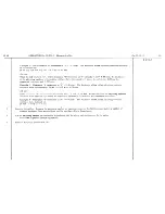
Страница 345: ...ENGINE ID 19 FITTING THE VALVES 5 SPRING COMPRESSOR sdld under No 1614 T Fig 2 Fig 3 RETAINER MR 4158 20 not sold 114...

Страница 346: ...HAND WHEEL 9 BRING THE SPRING 1 TO BE CHECKED TO THE LENGTH UNDER LOAD SHOWN IN THE TEXT READ THIS LENGTH OPPOSITE THE INDEX MARK 4 ON THE SCALE OF LENGTH 5 C READ ON THE SCALE 10 I d oa in kg OPPOSI...

Страница 347: ...NING 21 75 FT LBS 3 M KG 2nd TIGHTENING 43 5 FT LBS 6 M KG IT IS ADVISABLE TO TIGHTEN THE SCREWS IN THE ORDER INDICATED ABOVE THE TENSION OF TIGHTENING IS OF THE GREATEST NSABLE IMPORTANCE AND THE USE...

Страница 348: ...Fig1 EXTRACTING A GUIDE ENGINE ID 19 REPLACEMENT OF THE VALVE GUICES 8 Fig 2 _ FITTING AN INLET VALVE GUIDE Fig 3 FITTING AN EXHAUST VALVE GUIDE TOOLS sold under No 1644 T...

Страница 349: ...ENGINE REPLACEMENT OF THE VALVE GUIDES Fig 1 TOOLS GE sold under No 1644 T 1 1 i B 2 l I Dia 44 25 5 _ F H 8 across flats G Fig 2 _ REAMER sold under a 1 642 T ID 19 9...

Страница 350: ...OPERATION ID 1oc 3 15 Fig 1 17 27 22 10 16 ENGINE OIL PUMP Fig 2 21 19 ID 19 IO Fig 3 PRESSURE PAD 0 12 length 4Q Fig I EXTRACTOR sold under No 1964 T...

Страница 351: ...ve pump bv meons of on electric drill i Pressure gauge 0 56 Ibs per sq in WITH OIL OF SAE 20 VISCOSITY WARMED TO 60 50 C THE PRESSURE SHOULD BE 50 LBS PER SQ IN 3 5 KG CMZ AT 1000 R P M IF THIS PRESSU...

Страница 352: ...GE OF THE JOINT SHOULD BE PARALLELTOTHE FLAT ON THE CYLINDER BARREL BY HAND FIT THE JOINT AS FAR AS THE FIRST SHOULDER ON THE CYLINDER BARREL Fig 1 Fig 2 Fig 3 _ PUNCHED PLATE MR 4134 not sold COhiPLE...

Страница 353: ...ig 1 _ METHOD OF USING RING CLIP Internal chamfer towards the top CLIP FOR PISTON RINGS sold under No 1656 T Fig 2 _ RECTIFICATION OF A CAST BEARING STRAIGHT EDGE MR 3377 not sold DIAL GAUGE sold unde...

Страница 354: ...OPERATlObjS ID 100 3 ID ill 1 ENGINE ID 19 ASSEMBLY OF THE OIL SEALS 14 Fig 1 THE ENDS OF THE SHIM MUST NOT EXTEND UP TO THE ASSEMBLY FACE OF THE HALF SHELLS Fig 2 8 10 I shim J...

Страница 355: ..._ SPANNER sold under N0 1667 T hexagon 1 46 3 across flats ENGINE SETTING THE TIMING WHEELS Fig 2 POSITION OF TIMING MARKS ID 19 15 Fig 3 _ SPANNER sold under No 1 731 T SETTING GAUGE sold under No 16...

Страница 356: ...ig 2 SPANNER MR 3462 70 Fig 3 SPANNER not sold not sold L 87 L Hexagon 12 across flats _ _ _ z _ i sold under No 1645 T Fig 4 SPANNER sold under No 1603 T Fig 5 _ UNION SCREW MR 3705 Fig 6 SOCKET not...

Страница 357: ......

Страница 358: ...ENGINE STANDS FOR DISMANTLED ENGINE Fig 1 _ STAND MR 3053 170 not sold Frg 2 _ STAND MR 3053 160 160 not sold ID 19 18 FOR CONSTRUCTIONAL DIMENSIONS APPLY TO THE SERVICE DEPARTMENT...

Страница 359: ...ENGINE STAND FOR DISMANTLED ENGINE GEARBOX ASSEMBLY ID 19 19 I I THE TRUCK PERMITS I DISENGAGEMENT CF GEARBOX AFTER UNCOUPLING FROM __ r THE ENGINE STAND AND TRUCK sold under No 497 T...

Страница 360: ...JUSTMENT OF THE POSITION OF THE HIGH PRESSURE PUMP Fig 1 SETTING THE DIAL GAUGER Fig 2 _ TAKING THE MEASUREMENT Fig 3 FITTING THE PUMP ON THE ON THE CYLINDER BLOCK CYLINDER BLOCK TOOL sold under No 16...

Страница 361: ...OPERATION ID 100 1 ENGINE ID 19 CHECKING THE DISTANCE BETWEEN SUPPORT AND CROSSMEMBER 21 s I r I A I I I I I I I AGJUSTING FIXTURE sold under No 1698 T _ I s 1 _ I k 11 I I I I I I r I D C B A...

Страница 362: ...OPERATION ID 100 l ADJUSTING THE LONGITUD ENGINE ID 19 22 INAL POSITION OF REAR ENGINE SUPPORTS ADJUSTING FIXTURE sold under N0 169LT...

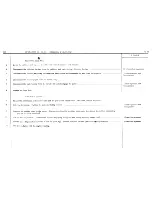
Страница 363: ...IO loo l ENGINE ID 19 ADJUSTING THE HEIGHT OF THE REAR ENGINE SUPeORTS 23 ADJUSTING FIXTURE sold under No 1698 T y Lr...

Страница 364: ...OPERATION ID 100 l ENGINE ID 19 ADJUSTING THE CENTRES OF THE REAR ENGINE SUPPORTS 24 ADJUSTING FIXTURE f sold under No 1698 T...

Страница 365: ...RATIONS IDl33 0 ENGJNE ID t9 ID l33 1 SPANNERS FOR ADJUSTMENT OF REAR ENGINE SUPPORTS 25 sold I la SPANNER under Ho 1982 T SPANNER under No 1699 SPANNER sold under No l699...

Страница 366: ...OPERATION ID 142 3 18 27 19 30 1 28 CARBURETTOR ID 19 SOLEX 34 PBIC 26 23 16 20 15 7 13 10 8 9 i i 1 i 1 I 22 6 3 4 21 14 16 1 1 1 29 22 5...

Страница 367: ...OPERATIONS ID 142 4 ENGINE ID 453 6 ACCELERATOR CONTROL 6 ID 19 27 d 6Omm I...

Страница 368: ...I 1 2 ENGINE HIOFILTRE AIR FILTER 11 4 9 5 9 7 6 0...

Страница 369: ...OPERATION ID 171 3 ENGINE ID 19 VOKES AIR FILTER 29...

Страница 370: ...OPE hT QNS ID 173 3 ID174 1 Fig 2 14 13 15 PETROL PUMP SECTION OF GUIOT PUMP ID 19 30 Fig I Fig 3 11 i _I_ 4 _ I...

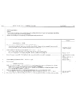
Страница 371: ...ID 173 3 PETROL PUMP ID 19 INSPECTION FOR LEAKS a b...

Страница 372: ...OPERATIm ID 211 3 ENGINE S E V DISTRIBUTOR Fig 1 ID 19 32 Fig 2 2 l 2 I LL L 28 T22 10 28 27 4 u 19 9 29 Fig 3 Fig 4 17 16 19 14 23 6...

Страница 373: ...OPERATION ID 211 3 ENGINE 1 19 DUCELLIER DISTRIBUTOR 33 35 id 0 10 4 5 8 1 1 I t 1 21 6 19 20 22 33 25 34 27 23 26 24 l 13 10 30 31 32 a 28 29...

Страница 374: ...9 34 BlSTRll3UTOR ADVANCE CURVES Fig 2 SUCTION ADVANCE CURVE Fig 1 CENTRIFUGAL ADVANCE CURVE advance in degrees 20 5 0 500 1ooo 1500 2000 r p m distributor advance in degrees 20 15 10 5 0 100 I 200 40...

Страница 375: ...OPERATIONS ID 231 3 ID 231 C ENGINE WATER PUtiF ID 19 35...

Страница 376: ...0 presrfit A ii I dia 30 I w 150 I dia 25 press fit ENGINE WATER PUMP ID 19 37 Fig 2 BOX SPANNER sold under No l646 T Rs 3 BUSH AND MANDREL MR 3676 270 not sold Fig4 _ EXTRACTOR TAP sold under No 2291...

Страница 377: ...OPERATIONS ID lOG 3 10312 3 CLUTCH ASSEMBLY ID 99 6 Fig 1 Fig 2 a b Fig 3 4 i 9 4 g f I I d 5 5 7 I II I I I y _ 5 __ _ TZ J i I I 3 i Y I GRINDTHE SAME AMOUNT OFF EACH OF THETWO FACES...

Страница 378: ...ING AND CLAMP sold under No 1704 T II _ I KINGS f OR CLEARANCE I __ I _ _ THE PLATE A IS TO BE SECURELY FIXED TO A BENCH THE TUBE B WILL PASS THROUGH THE BENCH AND WILL BE FIXED TO THE FLOOR INSTRUCTI...

Страница 379: ...ID 19 ADJUSTMENT OF THE TOGGLES 40 Fig 2 ASSEMBLY OF THE BLOCKS Fig 3 BLOCK MR 3457 100 Ftg 4 _ MANDREL not sold 176 0 7 5 SoId under No 1712 T I 0 14 I 8 8 0 17 5 5 2 0 7x100 J 170 30 thickness 30 3...

Страница 380: ...OPERATIONS ID 314 O ID 314 4 CLUTCH CLUTCH CONTROL li i lf ID 19 41 2 5 4 I a...

Страница 381: ...SUPPORT FIXTURE sold under No 1799 T GEARBOX ID 19 REMOVAL ANC REPLACEMENT 42 ENGINE STAND sold under No 1797 T CHAIN SLING sold under No 1697 T...

Страница 382: ...OPERATION ID 330 3 GEARBOX ASSEMBLY 9 8 7 10 8 6 16 32 33 17 16 15 14 13 12 b b b 1 1 1 19 113 23 109 107 108 ID 19 43 4 11 93 20...

Страница 383: ...32 33 104 44 39 37 35 17 16 15 14 13 SHAFTS Fig 1 _ MAIN SHAFT OPERATION ID 330 3 GEARBOX ID 19 Fig 2 _ BEVEL PINION SHAFT...

Страница 384: ...ERATION ID 330 3 GEARBOX ASSEMBLY OF PINIONS Fig 1 ID 19 44A Ftg 2 teeth entry at 15 teeth entry straight Fig 3 Fig 4 4th speed mainshaft pinion 3rd speed mainshaft pinion d b e a C Intermediate train...

Страница 385: ...OPERATIONS ID 133 l ID 3303 ID 3304 GEARBOX DIFFERENTIAL ID 19 1 56 49 52 53 48 4 5 3 61 i7 Fig 2 REVERSE GEAR 27 110 25 24 29 111 112 28 26 58 62 64 63...

Страница 386: ...gth 50 Fig 2 SETTING THE DIAL GAUGE 25 201 2 2 203 t Fig 4 ADJUSTMENT OF THE NEEDLE BEARING CAGE Fig 5 TOUCHE sold under No 2441 T 205 I lg 1 JI P AIC I cube wrruK I sold under No 1754 T I I I Licit 1...

Страница 387: ..._ OPERATIONS ID 330 3 ID 331 1 ID 331 3 REVERSE I GEARBOX COVER ID 19 46 LEVERS OPERATING THE SELECTOR SHAFTS view in direction of arrow F 3rd and 4th 83 I 9 82 1st and 2nd I 103 66 65 67 T 69...

Страница 388: ...OPERATIONS ID 330 3 ID 331 t ID 331 3 GEARBOX ii7 19 COVER 47 Fig 1 75 76 74 72 73 103 80 100 94 101 95 80 102 73 72 74 81 79 99 96 97...

Страница 389: ...OPERATIONS ID 330 2 GEARBOX ID 19 FIRST SPEED SELECTOR LEVER Fig 1 21 98 422 48 Fig 2 98 21...

Страница 390: ...OPERATIONS ID 231 4 ID 314 4 ID 330 2 ID 330 3 Fig 1 GEARBOX ID 19 CLUTCH HOUSING 49 Fg 3 Fig 2 n a7 aa 1 n 2 IhI 89 90 93...

Страница 391: ...T OF TOOTH CLEARANCE GEARBOX ID 19 ADJUSTMENT OF CROWN WHEEL AND BEVEL PINION 50 DIAL GAUGE sold under No 2437 T SUPPORT FOR DIAL GAUGE sold under No 2039 T EXTENSION sold under No 2439 T ADJUSTING FI...

Страница 392: ...NT OF THE DIFFERENTIAL BEARINGS 51 OPERATION Fig 1 _ MEASURING THE DEPTH OF THE HOUSING Ftg 2 _ MEASURING THE HEIGHT OF THE SHOULDER OF THEHUB SUPPORT FOR DIAL GAUGE sold under No 1166 T c D A LA 4 I...

Страница 393: ...TRACTION OF BEARING DIFFERENTIAL BEARING EXTRACTORBODY sold under No 1750 T SPLIT CDLLET AND RING sold under No 1753 T THRUST BLOCK sotd UP der No 1742 T Fiq 2 _ FITTING BEARING ROULEMENT MANDREL sold...

Страница 394: ...STAND MR 3053 130 not sold FOR CONSTRUCTIONAL DIMENSIONS APPLY TO THE SERVICE DEPARTMENT GEARBOX ID 19 STAND FOR GEARBOX FOR USE ON BENCH 53...

Страница 395: ..._ MANDREL MR 3676 30 Fig 3 _ SPANNER Flg 4 _ SPANNER not sold not sold sold under No 1734 T sold under No 1677 T machinc ccording to the tube dia 0 30 not mochlned r 2 at 45O I I 350 38 brut hexagon...

Страница 396: ...G GEARBOX VARIOUS TOOLS Fug1 MANDREL F g 2 _ MANDREL sold under No 1767 T sold under No 1772 T ID 19 55 Fig 3 _ SPANNER sold under No 1771 T THE BUSH C CENTRES THE SEALING JOINT AND THE MANDREL D ASSU...

Страница 397: ...OPERATIONS ID 330 3 GEARBOX ID 19 ID 331 3 ASSEMBLY OF THE LEVERS OPERATING THE SELECTOR SHAFTS 56 Fig 1 Fig 3 Lb Fig 2 Fig 4 Fig 5 _ MANDREL sold under No 1 793 T...

Страница 398: ...FRONT BEARING Fig 2 SPANNER MR 3691 80 EXTRACTOR BODY sold under No 1750 T Fig 5 SPANNER Sold under No 1705 T SPLIT COLLAR AND PRESSURE PAD sold under No 1738 T Fig 3 _ EXTRACTOR FOR BEVEL PINION SHA...

Страница 399: ...1 A FIXTURE sold under No 1683 T I Checking the position of the Driving Pulley ALIGNMENT OF THE PULLEYS Fig 2 Checking the position of the Water Pump Pulley Fig 3 ID 19 58 I a I __ i h i Checktng the...

Страница 400: ...OPERATIONS ID 334 o ID 334 1 1 GEARBOX GEAR CHANGE CONTROL ID 19 59 32 T...

Страница 401: ...OPERATIONS ID 334 O ID 334 l GEARBOX ID 19 GEAR CHANGE CONTROL 60 16 8 6 E 4 1 29 27 23 24 25 26 27...

Страница 402: ...VARIOUS TOOLS 61 Fig 1 _ SPANNER sold under No 2431 T Fig 3 SPANNER sold under No 221 9 T Spanner 2219 T a 9 8 Spanner 2220 T a I 15 8 Spanner 2221 T a 10 8 2 Spanner 2222 T a ls 8 Fig 2 CLAMP sold un...

Страница 403: ...ID 372 l ID 410 3 ID 413 1 8 FRONT AXLE ID 19 SECTIONS 62 23 24 7 OPERATIONS _ 22 i 29...

Страница 404: ...OPERATIONS FRONT AXLE ID 19 ID 410 3 SECTION OF THE UPPER BALL JOINTS 62A I D 413 1 I Fig 1 Fig 2 31 22 I Fig 3 ASSEMBLY OF THE WHEEL LOCKING SCREW FIXTURE sold under No 1868 T L I...

Страница 405: ...o 1856 T sold under N0 1857 T Fig 3 ADJUSTING THE UPPER BALL JOINT SETTING DIAL GAUGE MEASURING THE THICKNESS OF ARJUSTING WASHER USING THE BODY OF EXTRACTOR 1856 T DIAL GAUGE FOR THE DIMENSIONS OF so...

Страница 406: ...USTING FIXTURE sold under No 1867 T Fig 2 EXTRACTOR 6 c B C B sold under No 1964 T sold under No 1864 T noi sold 64 Fig 3 EXTRACTOR AND PRESSURE PAD Fig 4 SPANNER MR 3691 40 Fig s SPANNER sold under N...

Страница 407: ...FRONT AXLE SUPPORT FOR HALF AXLE Fig 1 SUPPORT MR 3053 120 not sold ID 19 65 1 METHOD OF USING SUPPORT...

Страница 408: ...Fig FRONT AXLE VARIOUS TOOLS I SPANNER Sold under No 1921 T Fig 2 ID19 66 SPANNER Sold under No 1920 T e LF I Tzc z 2 i 1922 T crew dia I8 I 150 length 60...

Страница 409: ...AND DISC MR 3676 140 Fig 2 _ METHOD OF USING Fig 3 MANDREL MR 3676 156 THE MANDREL MR 3676 150 not sold sharp edge removed fitting the seal 9 fitting the seal 10 _ _ _ _ I _ _ press fit and weld 0 35...

Страница 410: ...OVER 6 _ sold under No 1930 T 1st GREASE THE TAPER FITTING 2nd PUT THE DUST COVER 1 ON THE TAPER AS SHOWN Fig 1 3rd GRASP THE DUST COVER By THE LARGE DIAMETER AT a PULL FIRMLY OVER THE END lb 4th REMO...

Страница 411: ...sold under No 1866 I BRING THE ROD A INTO CONTACT WITH THE CUP OFJTHE ROD B THE HEAD D ONTHE ROD A ENGAGEDIN THESLOT E ON THE ROD B THE SETTING IS CORRECT WHEN THE DIMENSION f IS BETWEEN 24 75 AND 25...

Страница 412: ...OPERATIONS ID 420 l ID 420 3 ID 420 C ID 451 4 REAR AXLE lDl9 SECTION Oc HUB 70 DS 32 I 25 20 1 I 1...

Страница 413: ...OPER ATION3 ID 420 l ID 420 3 REAR AXLE ARM PIVOT BEARING ID19 71 33 34 52 24 23...

Страница 414: ...REAR AXLE METHOD OF SECURING THE ARM PIVOT BEARING Fig 1 SPANNER Fig 2 EXTRACTOR sold under No 1757 T sold under No ZOZO T ID 19 72 a I II I I 1 I 0 SUPPORT sold under No l922 T...

Страница 415: ...x 6 110 mm long pg I 7 I I I ri i ___ _ _ ____ ___ A my y 2 2 1 sheet steel 4 mm thick developed length 170 mm 3 2 split collorr4 mm thick 25 mm wide developed length 180 mm 4 2 split collars 4 mm th...

Страница 416: ...D 19 EXTRACTION OF THE HUB BRAKE DRUM 74 EXTRACTOR sold under No 2018 T Y _ y i 1 _ 1st PUT THE YOKE A BETWEEN THEARMANDTHEBRAKE BACKPLATE 2nd PUT THE EXTRAC IDR B ON THE HUB LOCKING IT TO THE YOKE BY...

Страница 417: ...ACTOR 1 1 PLACE THE SPLIT RING A WITHOUT THE SPINDLE B BEHIND THE RING C 2 PUT THE SPINDLE 6 IN THE SPLIT RING A SO AS TO SPREAD AND LOCATE THEM 3 FIT THE U PIECE D THE WASHER E SCREW UP THE NUT F NOT...

Страница 418: ...ARANCES 77 Fig 1 CALIBRATION OF DIAL GAUGE WITH BEARING Fig 3 FITTING THE BEARING OUTER RACES SCREW MR 4114 washer 79 5x275x15 L screw dia 27 x length 19 sold under Nta 1 Fig 2 EQUIPMENT FOR ADJUSTMEN...

Страница 419: ...USPENSION ID 19 HYDRAULIC SYSTEM rear suspension cylinder I _ v L A high pressure pump accumulator pressure distributor block mm feed two woy circulation high pressure exhaust return leakage return I...

Страница 420: ...OPERATIONS ID 372 l ID 410 l ID 433 O ID 433 l ID 433 3 rD 433 4 SUS_PENSION ID 19 FRONT AXLE SUSPENSION 79 38 10 3 41 39 40 35 Sb IIII II I 14 15 20 8 Id Ill In 13 16 4 19 32 22 21 23...

Страница 421: ...OPERATIONS ID 410 l ID 433 O ID 433 I ID 433 3 ID 433 4 SUSPENSION ID 19 ANTI ROLL BAR AND HEIGWT CORRECTOR CONTROL 80 Fig 1 123 F49 2 23 Fig 3 Fig 4 Fig 5 Q 19 i 18...

Страница 422: ...OFEHATIONS ID 420 l ID 434 l ID 434 4 ID 453 7 SUSPENSION REAR AXLE ASSEMBLY 6 4 a 10 Fig 2 b Fig 3 17 LJ 12 15 81 4...

Страница 423: ...OPERATIONS ID 420 l ID 433 O ID 433 3 SUSPENSION ID 434 I REAR SUSPENSION CYLINDER ID 19 82 Fig 2 Fig 3 A A 1 1 1 1 1 7 11 12 6 4 2 10 14...

Страница 424: ...0PEFtATloNs ID 437 0 SUSPENSION ID 19 ID 437 1 MANUAL HEiGHT CONTROL GEAR 83 Fig 29 20 20 30 27 24 19 25 23 Fig 2 a 32 1L I I 36 37 35...

Страница 425: ...1 5 4 6 Fig 1 Fig 2 _ _ _ __ ID 391 O ID 391 3 SUSPENSION HIGH PRESSURE PUMP ID 19 84 2 3...

Страница 426: ...OPERATIONS ID 391 O ID 391 3 SUSPENSION HIGH PRESSURE PUMP Fig 1...

Страница 427: ...OPERATIONS ID 391 O SUSPENSION IO 19 ID 391 3 ID 393 3 PRESSURE CONTROL VALVE AND PRESSURE DISTRIBUTION BLOCK 85 Fiq 1 ld Fig 2 Fig 3 8 e 1 4 3 17 21 18...

Страница 428: ...OPERATION ID 433 3 SUSPENSION HEIGHT CORRECTOR SUSPENSION CYLINDER ID 19 86 Fig 1 Fig 2 TB 6 1 4 5 3 13 Fig 3 2 b 2r 12 dll I 11 a 7...

Страница 429: ...FIN 1 STRAP WRENCH sold under No 2223 T I _ I i 1 0 1 k SUSPENSION ID 19 VARIOUS TOOLS 87 Fig 2 ASSEMBLY sold under No 2224 T sold under N0 1623 T...

Страница 430: ...SUSPENSION VARIOUS TOOLS ID 19 88 Ftg 1 _ FITTING THE METAL CUPS Fig 3 HOLDING THE CYLINDER IN A VICE I Fag 2 PRESS TOOL MR 3045 80 not sold Jot 1 Fig 4 WOOD JAWS MR 3407 30 not sold...

Страница 431: ...3 L3 k70 Fig 8 Ftg 9 t D 391 63 F y i l D43591 a i _ i L j ____ i I j ii i D LS3 131 a i i Y i j j I DLS3 132 a w D391 60 a Fig 11 _ CONE Flg 12 CONE sold under No 2225 T sold under No 2226 T ID 19 89...

Страница 432: ...OPERATIONS ID 100 l ID 330 l ID 440 0 ID 441s t ID 442 l ID 442 3 STEERING ID 19 ASSEMBLY 90 i 17 15 24 21 20 22 23...

Страница 433: ...ID 100 l ID 330 l ID 334 l ID 440 O ID 441 l I D 442 l ID 443 l STEERING ID 19 FITTING THE STEERING WHEEL 91 Fig 1 _ COMPRESSING TOOL sold under the No 1993 T Ftg 2 r a W...

Страница 434: ...ACTOR reld under No 1966 T STEERING VARIOUS TOOLS Fig 4 SPANNER sold under No 1854 T F19 2 EXTRACTOR sold under No l967 T Fig 5 MANDREL MR 3676 110 not sold r 150 ID 19 92 1 Fig 3 SPANNER cold under N...

Страница 435: ...OPERATIONS ID 100 l ID 330 4 ID 440 O 10442 4 STEERING ID 49 VARIOUS TOOLS 93 Fq 1 SUPPORT sold under No l999 T Fig 3 Fig 2...

Страница 436: ...OPERATIONS ID 443 l ID 443 3 STEERING SECTION OF THE RELAY i ID 19 94 46 53 142...

Страница 437: ...FIT THE POINT OF THE GAUGE PIN B IN THE CENTRE POINT OF THE RELAY SPINDLE 3 DETERMINE THE THICKNESS OF THE ADJUSTING WASHER 62 TO BE FITTED AT f 4 FIT THE WASHER 62 TIGHTEN THE SCREW C TIGHTEN THE SPI...

Страница 438: ...1 STEERING VARIOUS TOOLS Fig 1 SPANNER sold under No 1969 T Fig 2 SPANNER YR 3691 70 not sold Fig 3 _ BOX SPANNER sold under No 1988 T Fig 4 TUBE sold under No 1990 T...

Страница 439: ...a washer 3mm thick for adjusting bearing ADJUSTMENT OF THE PINION Fig 2 MEASURING THICKNESS OF ADJUSTING WASHER Fig 3 FITTING THE BALL BEARINGS IN POSITION FIXTURE sold under No 1996 T SUPPORT FOR DIA...

Страница 440: ...HYDRAULIC SYSTEM FOR BRAKES ID19 98 1st ARRANGEMENT high pressure exhaust return a two way flow feed a 2nd ARRANGEMENT front brake cylinder I _ 5 A _ _ ____ _ y _ rear brake cylinder I _I _ i master c...

Страница 441: ...OPERATIONS ID 330 l ID 330 2 ID 331 1 ID 451 O ID 451 1 ID 451 3 BRAKES 1019 FRONT BRAKE UNIT Fig 1 7 l2 Fig 2 1 30 32 30 32 c 41 16...

Страница 442: ...OPERATIONS ID 330 2 BRAKES ID19 ID 451 O ID 451 l FRONT BRAKE UNIT 100 ID 451 3 Fig 1 5 4 50 33 26 17 1 9 Fiq 2 Fia 3 1 20 23 13 35 Fig 5 15 40 47 46 49 45...

Страница 443: ...S FOR BRAKES 101 Fig 1 a FORK sold under No 2128 T Fig 2 _ LEVER sold under No 2127 T Fig 4 _ SPANNER sold under N0 2141 T I_ _ _ _ i i i i i j i N Fig 3 SPANNER WITH EXTENSION sold under No 2129 T 7...

Страница 444: ...OPERATIONS ID 420 3 ID 420 4 ID 451 4 BRAKES ID19 REAR BRAKE BACKPLATE 102 Fig 1 Fig 4 Fig 2 1...

Страница 445: ...BRAKES REMOVING AND FITTING THE RETURN SPRINGS Fig 1 METHOD OF USING PINCERS Flg 2 PINCERS sold under No 21 10 T ID19 103...

Страница 446: ...ING THE MANDREL MR 3700 120 Fig 2 _ MANDREL MR 3676 170 not sold _ I I Fig 3 _ MANDREL MR 3700 120 dia of drilling 102 I not sold pitch I dowels 10 dto 20 long dia of drilling 102J f LO 35 I 220 __ __...

Страница 447: ...BRAKES ID 19 RIVETTING THE BRAKE CAM PINS 105 Fiq 1 _ METHOD OF USE Fig 2 _ RIVET SE T MR 3354 2 not sold Fig 3 _ BLOCK MR 3354 40 not sold kn ed...

Страница 448: ...HEHEXAGONOFTHESTUB AXLE TIGHTEN THE SCREW D TURNTHEGAUGEONECOMPLETEREVOLUTlON WITH THE INDEX B HELD AGAINST THE DRUM MOVE TIlEBRAKE SHOES BY MEANS OF THE ADJUSTING CAM SD THAT THE 1NDEX B IS LEVEL WIT...

Страница 449: ...BRAKES ID 19 107 PEDAL GEAR...

Страница 450: ...OPERATION ID 453 3 BRAKES MASTER CYLINDERS ID19 108 Fig 1 7 8 c 9 11 6 3 b 5 a 2 10 4 1 22 j i Fg 2 24 f e d...

Страница 451: ...OPERATIONS ID 454 O BRAKES ID 454 1 ID19 109 ID 454 3 PARKING BRAKE CONTROL MECHANICAL Fig 1 Fig 2 18 F 9 18 14 11 20 24 7 16 Fig 3 Fig 4 I I 12 13 15 a...

Страница 452: ...OPERATIONS ID 454 O ID 454 1 ID 454 4 BRAKES CABLE ADJUSTMENT ID 19 110 I I I I 4 I I I...

Страница 453: ...ADJUSTMENTS ID 19 LIFTING POINTS ON THE BODY 111 Fig l LOCATION OF THE JACKING PAD Fq 2 JACKING PAD sold under No 2505 T...

Страница 454: ...____ I _ i j I j I i i ii ii i e i i i _ L fi _ __ _ THE CAMBER Fg 2 DETAILS OF GRADUATION THE PLUMBuNE MUST BE LEVEL WITH THIS MARK THE DIFFERENCE BETWEEN THE RH SIDE AND THE LH SIDE OF THE CAR MUST...

Страница 455: ...GAUGE RODS sold under No 2307 T ADJUSTMENTS ID 19 PRE ADJUSTMENT 0 F THE FRONT HEIGHT 113 J...

Страница 456: ...OPERATION ID 532 3 25 27 26 29 28 10 18 25 27 26 29 28 10 18 ELECTRICAL DUCELLIER DYNAMO 715842 34 20 3s 9 6 5 13 15 16 1...

Страница 457: ...OpERATlON ID 532 3 ELECTRICAL ID 19 OUCElLlER DYNAMO 7158A 115 29 32 1 1 12 39...

Страница 458: ...OPERATION ID 532 3 ELECTRICAL PARIS RHONE DYNAMO GllR91 25 28 30 29 27 19 18 5 11 Pi I 33 c...

Страница 459: ...OPERATION ID 532 3 ELECTRICAL ID19 PARIS RHONE DYNAMO GllR91 117 Fig 1 Fig 2...

Страница 460: ...OPERATION ID 533 3 ELECTRICAL DUCELLIER STARTER 6003A 6 29 10 4 ID 19 118...

Страница 461: ...OPERATION ID 533 3 ELECTRICAL DUCELLIER STARTER 6003A 16 22 21 9...

Страница 462: ...OPERATION IO 533 3 ELECTRICAL PARIS RHONE STARTER D11842 6 1 5 8 5 3 20 21 22 14 15 16 4 I I 1 T 1 I I 23 2 214 13 I I 2 19 17 18 11 12 13 ID 19 120 I...

Страница 463: ...OPERATION ID 533 3 ELECTRICAL ID19 PARIS RHONE STARTER DllB42 121 Fig 1 Fig 2 16 21 19 18 14 15 Rg 3 2o 28 8...

Страница 464: ...RICAL BENADA PINION Fig 3 I Yg 6 _ SUPPORT MR 3526 13 k23 I Fig 7 LEVER MR 3526 12 66 L ID 19 121A Fig 4 non vendu V 20 I c 56 i channel iron 5 50x25 Fig 8 SUPPORT MR 3526 11 not sold rI 2 hex nuts 14...

Страница 465: ...FIELD COILS AND POLE PIECES 122 Fig l FORMING THE COILS I IPoris Rhone I Duccllier I Starter A Dynomo B d 72 5 68 Fig 2 FITTING THE POLE PIECES MR 16013 MR 1601 2 MR 1601 3 MR 1601 4 tools not sold mi...

Страница 466: ...ELECTRICAL WIRING DIAGRAM FRONT HARNESS 10 c s t 15 4 47 l I ID 19 123...

Страница 467: ...ELECTRICAL WIRING DIAGRAM REAR HARNESS 28 __ P 1 I 6 I ID 19 124 33 c J _ ___ _ J r 4 I 29 30...

Страница 468: ...HYDRAULIC ID19 TEST BENCH 125 CONNECTION OF THE IS00 P S I 100 kg cm 2 GAUGE...

Страница 469: ...M2 HYORAUL IC ID 19 TEST BENCH 126 CONNECTION OF THE 3000 P S I 200 kg cm2 GAUGE b...

Страница 470: ...HYDRAULIC TEST PIPES AND UNIONS ID19 127 K sold under the No 2295 T...

Страница 471: ...OPERATION ID 391 O HYDRAULIC HIGH PRESSURE PUMP ID19 128 INSPECTION FOR LEAKAGE S...

Страница 472: ...ID 391 O HYDRAULIC 1019 129 PRESSURE CONTROL VALVE INSPECTION OF THE CUTTING IN AND CUTTING OUT PRESSURES AND FOR LEAKAGE F e d c b...

Страница 473: ...OPERATION ID 393 O HYDRAULIC ID19 PRESSURE DlSTRl6UTlON BLOCK 130 INSPECTION FOR LEAKAGE...

Страница 474: ...OPERATION ID 393 0 HYGRAULIC 3 19 PRESSURE CISTRl8UTION BLOCK 131 INSPECTION OF THE VALVE SETTINGS f I L r f 1 r L J 4 I I i L _I___ _ _ _ _ _I_ __ _ _ A 1 2 1...

Страница 475: ...0DE A T ON IC 391 0 HYDRAULIC MAIN ACCUMULATOR PRESSURE TEST ID 19 132...

Страница 476: ...ID 391 o HYDRAULIC _ ID 19 PRESSURE CONTROL VALVE 133 INSPECTION OFTHECUT INANCCbT OUT AND FOR LEAKAGE ONTHE CAR...

Страница 477: ...OPERATION ID 433 O HYDRAULIC SUSPENSION CYLINDE R INSPECTION FOR LEAKAGE B I SUPPORT eold under ID 19 134 CEV i __ _ _ _________________ _ c...

Страница 478: ...ING AT THE FRONT Fig 2 LIFTING AT THE REAR x q r INSERT AT b BETWEEN THE CHASSIS AND WOODEN PLANKS A THICKNESS OF SACKING I Ill _ _ __ _ __ ___ __ I _ __ FIT THE HOOKS ON THE LOWER ARMS __ _ _ __ _ _...

Страница 479: ...WING TRIANGLE Second qwlity Martin steel 2 steel weld Assemble the rings 5 before welding 5 CONNECTING LINK 6 Dieces EXTENSION TUBE i 56 J Second quality chain 1 792 mm between connecting links 12 CNM...

Страница 480: ...et steel 1 3mm sheet steel G 1 Cold drawn weldless steel tube 30 x 39 l 4mm shy steel l Steel th ckness as requ red I 11 C B A i D Drawn tube left hand Rear distance piece for draw tubes Fixing plate...

Страница 481: ......

Страница 482: ...rox I y shape resulting from flattening tube l p p r and Z curves resulting from flattening tube QO ax t I 323 I 70 car centreline shape resulting from car centreline 70 approx ___ MODIFICATION TO REA...

Отзывы: