background image

iDP-562 User’s Manual

CITIZEN

8

5. Serial Interface

5.1 Serial Specifications

(1)  Synchronous                  Asynchronous

(2)  Baud rate

150, 300, 600, 1200, 2400, 4800, 9600 BPS
One of the above baud rates is selected by users.

(3)  Data Format

Start bit:   1 BIT
Data bit:   7 or 8 BIT
Parity bit:  Odd number parity, even number parity or no parity check, one of which is selected by users.
Stop bit:   1 or 2 BIT

(4)  Signal level

RS-232C               MARK = 1 (-3V ~ -12V)

SPACE = 0 (+3V ~ +12V)

CURRENT LOOP MARK = 1 (Current)

SPACE = 0 (Non-current)

TTL                 

MARK = 1 (Open collector)
SPACE = 0 (Open collector)

(5)


DTR signal
RS232C and TTL

MARK: Not ready for DATA receipt
SPACE: Ready for DATA receipt

Current loop

When current between connector 17 pin and 24 pin is
MARK (Current): Ready for DATA receipt
SPACE (Non-current): Not ready for DATA receipt

Содержание iDP-562 Series

Страница 1: ...DOT MATRIX PRINTER MODEL iDP 562 ...

Страница 2: ... 1993 EMC EN55022 1994 Class B EN61000 3 2 1995 EN61000 3 3 1995 EN50082 1 1992 IEC801 2 1991 4KV CD 8KV AD IEC801 3 1984 3V m 27MHz 500MHz IEC801 4 1988 0 5KV Signal Line 1KV AC mains Supplementary Information The product complies with the requirements of the Low Voltage Directive 73 23 EEC 93 68 EEC and the EMC Directive 89 336 EEC 92 31 EEC 93 68EEC Place Tokyo Japan Date January 1996 Signature...

Страница 3: ...s that could result in a risk of fire or electric shock Never spill liquid of any kind on the product Except as explained elsewhere in this manual don t attempt to service this product yourself Opening and removing those covers that are marked Do Not Remove may expose you to dangerous voltage points or other risks Refer all servicing on those compartments to service personnel Unplug this product f...

Страница 4: ...Changes or modifications not expressly approved by the party responsible for compliance could void the user s authority to operate the equipment iDP 562 RSL RS iDP 562 CNL CN type This digital apparatus does not exceed the Class A limits for radio noise emissions from digital apparatus set out in the Radio Interference Regulation of the Canadian Department of Communications Le Présent appareil num...

Страница 5: ...Switch 9 5 3 Connectors and Signals 10 5 4 Interface Circuit 10 5 5 Current Loop and TTL 11 5 5 1 Interface Loop 11 5 5 2 Setting of Preset jumper 12 5 6 DATA Construction 14 5 6 1 Serial Data format 14 5 6 2 Detection System for Error 15 5 6 3 Input Control and Buffering 15 6 Parallel Interface 17 6 1 Description on Input Output Signals 17 6 2 Setting the Dip Switch 18 6 3 Connector and Pin Assig...

Страница 6: ... data recording on normal and carboned roll papers Use this printer properly after reading carefully the manuals of the printer and your computer 1 1 Features The printer features the following 1 Compact dot matrix printer 2 Light weight 3 Low power consumption 4 Prints in two colors of red and black 1 2 Accessories Check all your accessories with the following list If anything is missing contact ...

Страница 7: ...or less 10 Ink Ribbon Cassette In red and black Width 13 mm 11 Voltage 120V 10 50 60 Hz for UL CSA 230V 10 50 60 Hz for EP 12 Power 35 W max 13 Weight 2 3 Kg 5 1 lbs Approx 14 Dimensions 240 mm W 231 5 mm D 111 5 mm H 9 4 W 9 1 D 4 4 H 15 Interface Serial Interface RS 232C TTL Level Current Loop NOTE Current Loop and TTL are a factory option 8 bit parallel Interface 16 Operating Temperature 5 C 35...

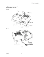
Страница 8: ...iDP 562 User s Manual CITIZEN 3 3 Appearance and Parts Name 3 1 Appearance and Parts name Front view Fig 1 Rear view Fig 2 ...

Страница 9: ...n When this ALARM state happens printing and Line Feed operation is suspended For a release from an ALARM state push SEL switch or turn off the power switch once and turn on again 6 LF Switch Use this switch for paper feeding and line spacing when the printer is in DESELECT state 7 SEL Switch When this switch is pressed the printer enters SELECT ON LINE status When pressed again the printer enters...

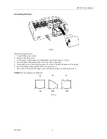
Страница 10: ...ontinued for many hours be careful not touch printer head as it might be hot 1 Remove the printer cover 2 While inserting the ribbon into the space between the print head and the ribbon guide press the cassette into the holder unit it clicks into place Ref to Fig 3 4 3 Turn the cassette ribbon knob in the direction of the arrow to take up slack in the ribbon Fig 3 Fig 4 ...

Страница 11: ...nal center line as shown in Fig 6 4 Insert the paper into insertion inlet on the rear side of the printer 5 Turn on the power switch And then press LF switch to forward the paper into the printer 6 Fix the roll paper at paper holder and set the printer cover 7 Press the LF switch until the paper comes out from the paper exit of the printer cover Caution Do not pull paper to backward Fig 6 ...

Страница 12: ...ing press the either switch 4 4 Cautions 1 Never operate your printer without loading paper and setting Ink Ribbon Cassette Any printing without paper and ink ribbon cassette may cause damage of printer head 2 Replace the Cassette before ink ribbon is worn with rents 3 Be careful not to drop any foreign matters such as paper clips pins and the like into your printer Those can cause mechanical trou...

Страница 13: ...ty even number parity or no parity check one of which is selected by users Stop bit 1 or 2 BIT 4 Signal level RS 232C MARK 1 3V 12V SPACE 0 3V 12V CURRENT LOOP MARK 1 Current SPACE 0 Non current TTL MARK 1 Open collector SPACE 0 Open collector 5 DTR signal RS232C and TTL MARK Not ready for DATA receipt SPACE Ready for DATA receipt Current loop When current between connector 17 pin and 24 pin is MA...

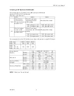
Страница 14: ...ank ON immediately after full buffer printing OFF LF code is void OFF LF code is valid LF code is valid LF code is selected by the DSW 2 and 3 ON LF code is valid ON LF code is void It is recommended to set the DIP switches in accordance with your host s output DATA format DATA Form DSW 1 DSW 2 DSW 3 DATA CR OFF OFF OFF DATA LF DATA CR LF ON OFF OFF DATA LF CR Foreign character USA GERMANY FRANCE ...

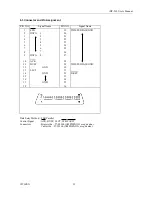
Страница 15: ...forms to EIA RS 232C level 2 Signal of CURRENT LOOP should be restricted within 10 20 mA 3 Keep signal pin No 3 at MARK status when no transfer of DATA 4 Selection of modes those are RS 232C CURRENT LOOP and TTL can be made by the preset jumper Please refer to Setting of Preset Jumper Compatible Connector D Subconnector Printer 17LE 13250 AMPHENOL or equivalent Cable Side 17JE 23250 AMPHENOL or eq...

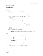
Страница 16: ...nterface Circuit a Current Loop Input RD Printer side Computer side Output DTR Note Resistance should be set so that Current Loop is restricted within 10 20 mA b TTL Input RD Printer side Computer side Equivalent to 7407 Output DTR FAULT Note Output is open collector ...

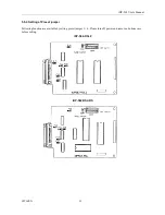
Страница 17: ... User s Manual CITIZEN 12 5 5 2 Setting of Preset jumper Following function are available by setting preset jumper 1 6 Please turn off power and remove a bottom case before setting iDP 562 RSL2 iDP 562 RSL RS ...

Страница 18: ...A 5 A B Both A and B can be set B position A position A B DATA can be transferred at DTR SPACE A RS 232C TTL level DATA can be transferred at DTR MARK 6 CURRENT LOOP DATA can be transferred at DTR MARK B RS 232C TTL level DATA can be transferred at DTR SPACE CURRENT LOOP At shipping all of preset jumper are set as A ...

Страница 19: ... stage When signal level is MARK continuous search for START BIT is made for the next bit 2 DATA BIT PARITY BIT DATA BIT and PARITY BIT are checked out every 1 2 BIT from the half point of START BIT b Signal level of these points MARK 1 SPACE 0 are read as input DATA The sequence of these BIT is BIT 0 BIT 1 PARITY BIT from START BIT 3 STOP BIT STOP BIT is 1 or 2 BIT and its signal level is MARK If...

Страница 20: ...rms the user this error In this case FAULT signal is SPACE DTR signal is BUSY and the machine becomes deselect condition ALARM condition will be released by depressing SEL Switch after removing the trouble at the printer The machine is now SELECT condition and starts to input DATA 5 6 3 Input Control and Buffering DATA receipt is controlled by each character In case the connected computer neglects...

Страница 21: ... The printer continues BUSY condition for receiving 2nd BYTE of DATA 3 The computer transfers 3rd BYTE of DATA after checking READY condition The printer expects Double Buffer transfer at the first stage Therefore after completion of 1st BYTE of DATA reception the printer waits for 2nd BYTE of DATA The printer recognizes Single Buffer transfer for the absence of START BIT after 1 2 STOP BIT ...

Страница 22: ...he printer is ready to receive additional data or function codes This signal is normally HIGH This is activated when signal is LOW The printer will not transmit this signal when DC3 code is received under SELECT state BUSY This is an output signal from the printer When the printer is BUSY state the signal is HIGH FAULT This is an output signal from the printer indicating printer FAULT state The si...

Страница 23: ... OFF CR code is valid ON CR code is valid ON CR code is void CR code is ignored When LF code comes LF code is valid immediately after full When the buffer is blank ON LF code is selected buffer printing by the DSW 2 and 3 OFF LF code is void OFF LF code is valid ON LF code is valid ON LF code is void It is recommended to set the DIP switches in accordance with your host s output DATA format DATA F...

Страница 24: ...4 22 5 23 6 24 7 25 8 DATA 1 2 3 4 5 6 7 26 9 DATA 8 27 ____ 10 ACK 28 11 BUSY 29 TWISTED PAIR GND 12 GND 30 13 SLCT 31 ______ 14 32 FAULT 15 33 16 GND 34 17 GND 35 18 36 Data Entry Method 8 Bit Parallel Control Signal ACK BUSY SLCT STB FAULT Connectors Printer side 57 40360 AMPHENOL or equivalent Cable side 57 30360 AMPHENOL or equivalent ...

Страница 25: ... input output signals are of TTL level HIGH level 2 0 V MIN LOW level 0 8 V MAX b Output Signal Level HIGH level 2 4 V MIN LOW level 0 4 V MAX c Input Output Conditions All the input signals are pulled up by 1 K ohms Fig 7 Fig 7 All the output signals are pulled up by 3 3 K ohms Fig 8 Fig 8 ...

Страница 26: ...Chart 1 Input Data and print timing T1 T2 T3 0 5µs MIN T4 100 ns MAX T5 7µ TYP T6 1100 ms MAX 400 µ MAX When data is stored in input buffer ______ 2 FAULT and SEL switch T1 500 ms TYP T2 10 ms MIN T3 550 ms TYP Note preset by SEL is done manually ...

Страница 27: ... Carries out from feed performance after printing DC1 11 Makes the printer SELECT ON LINE state Only this code can be accepted irrespective of DESELECT OFF LINE state DC2 12 Red printing is specified released Designation release alternative of red one line printing is possible with this code DC3 13 Makes the printer DESELECT ON LINE state Designation release of reverse printing DC4 14 Designation ...

Страница 28: ...de 2 Enhanced Character Print Mode Designation RS 1E DATA CR 0D All the print data which follow RS code are enhanced and are reversed to standard character by US code You can print the both standard and enhanced characters in one line Automatic printing is carried out when full column data 40 columns in standard character is input This RS code is released automatically after printing For 8 BIT DAT...

Страница 29: ...1 n1 240 Any numbers other than the above comes to 240 5 Graphic Print Data Printing in seven lengthwise dots by 240 rows can be made in one line The 7 lengthwise dots are input as the graphic print data The data are computed as follows The position as traced from the home position Correspondence of headpin to graphic print data As will be understood from the above the data are used in which the f...

Страница 30: ... The top of form for the next page is made in accordance with the page length which was specified with ESC C n Top of position of the page is determined when power is turned on or when page length is specified with ESC C n 8 Canceling CAN 18 All the data input in one line prior to CAN are cleared entirely with this code 9 Line Spacing Designation ESC 1B 1 31 With this code 2 75mm line spacing can ...

Страница 31: ... home position 2 Printer becomes SELECT ON LINE condition 1 3 Print buffer function is cleared 4 Standard character mode is set 5 66 per lines per page is set 6 The first line is set at the present line 7 Designation of reverse and red printing is cleared 8 For 7 BIT DATA character code of SI is applied 1 Printer becomes DESELECT OFF LINE condition Model iDP 562 PSL2 type only ...

Страница 32: ...iDP 562 User s Manual CITIZEN 27 9 Character Code Table 1 Character Code Table ...

Страница 33: ...iDP 562 User s Manual CITIZEN 28 2 Foreign Character Designation of characters can be made for four languages by ON and OFF of Dip switch ...

Страница 34: ...iDP 562 User s Manual CITIZEN 29 3 Character Code Table for 7 BIT DATA SI Side SO Side ...

Страница 35: ...ZEN 30 10 Maintenance With respect to maintenance The mechanical part of the printer must be free from dirt and dust Remove the printer cover periodically to clean printer mechanism with soft brush to eliminate any dirt and dust ...

Страница 36: ...Information Systems Division CBM Bldg 5 68 10 Nakano Nakano ku Tokyo 164 0001 Japan Head Office Tel 81 3 5345 7540 Fax 81 3 5345 7541 70903330 09 20000210 5300 0040 005 83 Printed in Japan ...

Отзывы: