background image

                                                                iDP-3545/3546 Service Manual
                                                                                    

                                                                                    CITIZEN

8

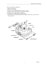
6. How to remove the PE Switch
 1) Remove the Printer Unit.
 2) Remove the Printer Mechanism.
 3) Remove the PE sensor connector(2pin) from the Control Board.

4) Remove the Vinyl Tape.
5) Push the Switch Holder the arrow(1) direction to remove the Hooks(3) from the Chassis.
6) Rotate the Switch Holder the arrow(2) direction, then it can be removed easily.

Содержание iDP-3545 Series

Страница 1: ...Service Manual Model iDP 3545 3546 Rev 0 00 Newly issued on Sep 22 1997 Japan CBM Corporation Information Systems Div...

Страница 2: ...iDP 3545 3546 Service Manual CITIZEN 2 Contents 1 Disassembly and Assembly 3 2 Parts list 10 3 Parts Position 21 4 Circuit Diagram 25...

Страница 3: ...iDP 3545 3546 Service Manual CITIZEN 3 1 Disassembly and Assembly...

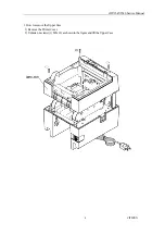
Страница 4: ...iDP 3545 3546 Service Manual CITIZEN 4 1 How to remove the Upper Case 1 Remove the Printer Cover 2 Unfasten 4 screws 1 M3x12 as shown in the figure and lift the Upper Case...

Страница 5: ...in the figure 3 Lift the Printer Unit in the arrow position for removal 4 Remove the AC Cord form the Lower Case 3 How to remove the Printer Mechanism 1 Unfasten 2 screws 1 M3x14 as shown in the figur...

Страница 6: ...remove the Shield plate 3 To remove the Control Board unfasten 2 screws 1 4 Disconnect some connectors as below IDP 3545 For Printer Mechanism 3 17pin 4 7pin For PE sensor 5 2pin IDP 3546 For Printer...

Страница 7: ...ove the AC Cord Cord bush from the Chassis by some tool 4 Unfasten 2 screws 1 M4x6 which are for Transformer mounting 5 Unfasten a screw 2 M3x8 which is for Heat Sink 6 Unfasten a screw 3 M4x6 which i...

Страница 8: ...r Unit 2 Remove the Printer Mechanism 3 Remove the PE sensor connector 2pin from the Control Board 4 Remove the Vinyl Tape 5 Push the Switch Holder the arrow 1 direction to remove the Hooks 3 from the...

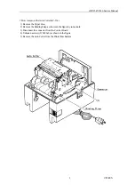
Страница 9: ...Auto Cutter AC 134 1 Remove the Upper Case 2 Remove the Binding Strap as shown in the figure by some tools 3 Disconnect the connector from the Control Board 4 Unfasten a screw 2 M2 6x6 as shown in the...

Страница 10: ...iDP 3545 3546 Service Manual CITIZEN 10 2 Parts list...

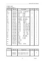
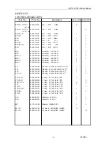
Страница 11: ...4035 690 FG plate 1 1 6 E 5117 050 Switch holder 1 1 7 E 5102 480 PE Switch 1 1 8 E 5071 130 Switch knob 1 1 9 E 5101 390 PE spring 1 1 25 E 6101 115 Bush SR4N4 for 120V 1 1 26 E 6101 120 Bush SR5N4 f...

Страница 12: ...iDP 3545 3546 Service Manual CITIZEN 12...

Страница 13: ...iDP 3545 3546 Service Manual CITIZEN 13...

Страница 14: ...2 C 5 E 2230 050 El cap FAC 228M 63V 1 1 C 6 E 2220 050 C cap FCC 101 J 50V 1 1 C 7 E 2230 060 El cap FAC 105 M 50V 1 1 C 8 E 2230 070 El cap FAC 477 M 35V 1 1 C 9 E 2230 080 El cap FAC 338 M 16V 1 1...

Страница 15: ...2 IC 10 E 2010201 IC HD7406P 1 IC 12 102 E 201 811 IC HD74LS373P 2 IC 101 E 202 830 IC TA8428K 1 1 IC 103 E 101007 IC M5M28C64 1 1 XLS28C64P 150 28C64A 15P TR 1 4 101 E 359 041 Tr 2SC945P 5 TR 1 7 101...

Страница 16: ...y AR 103 3 1 1 RA 6 7 E 3500 260 Re array AR 332 8 2 RA 8 E 3500 280 Re array AR 332 6 1 C 1 E 2230 200 El cap FAC 476 M 35V 6 3 11 1 1 C 2 E 2230 020 EL cap FAC 107 M 16V 6 3 7 1 1 C 11 E 2230 190 El...

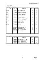
Страница 17: ...Connector 57GE40360 751 1 CN 4 E 48000280 Connector FCN 674J025 L C 1 CN 6 E 48000565 Connector 285D 9660J 101 1 1 DS 1 E 5103 520 Dip SW KSD 10 1 1 DS 2 E 5103 460 Dip SW SD 08ZL 1 NLCB E 8035 010 Ca...

Страница 18: ...2 IC 10 E 2010201 IC HD7406P 1 IC 12 102 E 201 811 IC HD74LS373P 2 IC 101 E 202 830 IC TA8428K 1 IC 103 E 101007 IC M5M28C64 1 1 XLS28C64P 150 28C64A 15P TR 1 4 101 E 359 041 Tr 2SC945P 5 TR 1 7 101...

Страница 19: ...3500 260 Re array AR 332 8 2 RA 8 E 3500 280 Re array AR 332 6 1 C 1 E 2230 200 El cap FAC 476 M 35V 6 3 11 1 1 C 2 E 2230 020 EL cap FAC 107 M 16V 6 3 7 1 1 C 11 E 2230 190 El cap FAC 226 M 16V 4 7...

Страница 20: ...57GE40360 751 1 CN 4 E 48000280 Connector FCN 674J025 L C 1 CN 5 Connector 5267 04A 1 1 CN 6 E 48000565 Connector 285D 9660J 101 1 1 DS 1 E 5103 520 Dip SW KSD 10 1 1 DS 2 E 5103 460 Dip SW SD 08ZL 1...

Страница 21: ...iDP 3545 3546 Service Manual CITIZEN 21 3 Parts Position...

Страница 22: ...iDP 3545 3546 Service Manual CITIZEN 22 SILK DRAWING 1 PARALLEL Please refer the parts list regarding actual parts assembling location...

Страница 23: ...iDP 3545 3546 Service Manual CITIZEN 23 2 SERIAL Please refer the parts list regarding actual parts assembling location...

Страница 24: ...2 1 2 3 4 2 iDP 3545 3546F 40RF TF 120V 230V IEA B FOR EMULATION RF CBM mode SF STAR mode TF ESC POS mode JP1 1 2 3 4 JP2 1 2 3 4 JP3 1 2 3 4 JP4 1 2 5 6 3 4 JP5 1 2 RS 232C 3 4 CURRENT 1 2 1 2 JP6 1...

Страница 25: ...iDP 3545 3546 Service Manual CITIZEN 25 4 Circuit Diagram...

Страница 26: ...iDP 3545 3546 Service Manual CITIZEN 26 BLOCK DIAGRAM...

Страница 27: ...iDP 3545 3546 Service Manual CITIZEN 27 CIRCUIT DIAGRAM POWER SUPPLY 120V...

Страница 28: ...iDP 3545 3546 Service Manual CITIZEN 28 CIRCUIT DIAGRAM POWER SUPPLY 230V...

Страница 29: ...iDP 3545 3546 Service Manual CITIZEN 29 CIRCUIT DIAGRAM CONTROL BOARD iDP 3545 3546 PF...

Страница 30: ...iDP 3545 3546 Service Manual CITIZEN 30 CIRCUIT DIAGRAM CONTROL BOARD iDP 3545 3546 RF...

Отзывы: