background image

- vi - 


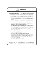
WARNING


n

  Never perform the following.    If not avoided, these may cause damage or 

trouble to the printer or cause the printer to overheat and release smoke 
and cause burns or an electrical shock.    If the printer is damaged or is 
malfunctioning, be sure to turn the power off and remove the power cord 
from the outlet, then consult our service personnel. 

·

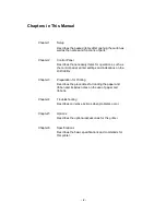
  Do not jolt or impact to the printer by stepping on, dropping or hitting 

the printer. 

·

  Do not place the printer in a poorly ventilated area, or shut off the air 

vent of the printer. 

·

  Do not place the printer where chemical reactions occur, such as in 

laboratories or where air is mixed with salt or gas. 

·

  Do not use a power voltage or frequency other than those specified. 

·

  Do not plug/unplug the power cord or attach/detach the interface 

cable by simply grabbing the power cord or interface cable.    Do not 
pull or carry the printer when the tension of the power cord or 
interface cable is increased. 

·

  Do not drop or put foreign matter such as clips and pins into the 

printer.    This may cause problems. 

·

  Do not plug the power cord into an outlet with many loads. 

·

  Do not spill drinks such as tea, coffee and juice on the printer or spray 

insecticide on the printer.    If drink or water is spilled, first be sure to 
turn the power off and remove the power cord from the outlet, then 
consult our service personnel. 

·

  Do not disassemble or modify the printer. 


n

  Discard or safely store the plastic packing bag.    This bag should be kept 

away from children.    If the bag is pulled over a child’s head, it may cause 
suffocation. 


Содержание CLP-6401

Страница 1: ...CLP 6401 User s Manual C ITOU...

Страница 2: ...operated in a commercial environment This equipment generates uses and can radiate radio frequency energy and if not installed and used in accordance with the instruction manual may cause harmful inte...

Страница 3: ...cables to connect this device to computers Any changes or modifications not expressly approved by the grantee of this device could void the user s authority to operate the equipment ETAT DE CONFORMIT...

Страница 4: ...nsion cord is used with this product make sure that the total of the ampere ratings on the products plugged into the extension cord do not exceed the extension cord ampere rating Also make sure that t...

Страница 5: ...tional products and consumable supplies other than the designated products contained herein 6 Do not handle disassemble or repair the parts other than those specified in this manual 7 We are not liabl...

Страница 6: ...se or improperly following instructions is described below This is a mark to call attention to the reader SAFETY SIGNS must be strictly observed WARNING Indicates a situation which if not observed and...

Страница 7: ...ltage or frequency other than those specified Do not plug unplug the power cord or attach detach the interface cable by simply grabbing the power cord or interface cable Do not pull or carry the print...

Страница 8: ...ked in thinner trichloroethylene benzine ketone or similar chemicals 7 Do not use the printer where there is a lot of oil iron particles or dust 8 Operate the control panel properly A careless rough h...

Страница 9: ...s air vent to be blocked by a wall or other object 6 Do not place anything on the top printer 7 Do not place the printer near a radio or television and do not use the same wall outlet for the printer...

Страница 10: ...nel printer settings and indications on the LCD LEDs Chapter 3 Preparation for Printing Describes the procedures for loading the paper and ribbon and includes notes on the use of paper and ribbons Cha...

Страница 11: ...1 8 Chapter 2 Control Panel 2 1 2 1 Control Panel 2 2 2 2 LCD LED Indications and Adjustment Controls 2 3 2 3 Normal Operating Mode 2 3 2 4 Printer Setup Mode 2 4 2 5 Self Test Mode 2 4 2 6 System Ma...

Страница 12: ...User Options 5 3 PCMCIA Memory Card 5 3 Chapter 6 Specifications 6 1 6 1 Main Specifications 6 2 6 2 Interface 6 6 6 2 1 System configuration 6 6 6 2 2 Specification of interface 6 7 6 2 3 RS 232C loo...

Страница 13: ...xii...

Страница 14: ...1 1 Chapter 1 Setup 1 1 Confirmation of Carton Contents 1 2 1 2 Part Names and Functions 1 3 1 3 Connection to Power 1 7 1 4 Connection to a Computer 1 8...

Страница 15: ...y the foam packing material which may break causing the printer to drop Check that the following accessories are included with the printer in the carton Power cord 1 pc Paper core 1 pc User s manual t...

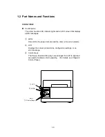
Страница 16: ...ssages LEDs One LED is the power indicator and the other is the error indicator LCD Displays the current printer status configuration settings or an error message Control keys The Pause Feed and Stop...

Страница 17: ...1 4 INSIDE VIEW Ribbon i d Open lever Offset verification window Ribbon holder Paper holder Roll guide Roll holder Cover...

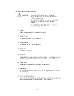
Страница 18: ...lder To attach the ribbon See Chapter 3 Ribbon winder To wind the ribbon See Chapter 3 Roll holder Holds the roll of paper Roll guide Guides the roll of paper to be set on the roll holder The roll gui...

Страница 19: ...A memory card from exposure to dust and foreign matter To install a PCMCIA memory card first unhook this cover then slide it out n Power switch To turn on off the power n Power inlet To connect the po...

Страница 20: ...ay be generated and there will be danger of electric shock Connect to an AC outlet as follows 1 Check that the power switch on the printer is set to OFF 2 Connect the connector of the power cord to th...

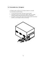
Страница 21: ...1 Turn off both power switches of the printer and the computer 2 Connect the connector of one end of the interface cable to the interface connector at the lower side of the printer and secure it with...

Страница 22: ...pter 2 Control Panel 2 1 Control Panel 2 2 2 2 LCD LED Indications and Adjustment Controls 2 3 2 3 Normal Operating Mode 2 3 2 4 Printer Setup Mode 2 4 2 5 Self Test Mode 2 4 2 6 System Maintenance Mo...

Страница 23: ...e left side of the control panel there are three adjustment controls paper gap black line and LCD contrast Exterior view of the control panel Serial interface connector Parallel interface connector Pa...

Страница 24: ...t 2 3 Normal Operating Mode When the power is turned on the printer enters normal operating mode The control keys function as follows n Pause key Temporarily pauses printing Pause is displayed on the...

Страница 25: ...auto cutter ON OFF etc n Pause key Selects the mode n Feed key Selects the mode item n Stop key Saves settings and returns the printer to normal operating mode Mode item Indication Direct thermal the...

Страница 26: ...cation values Mode of printing Direct Thermal or Thermal Transfer the type of media Gap Black Line with sensor voltage values checks the head and even tells you the number of mm s of material that hav...

Страница 27: ...ring this mode the printer will display the first of several parameters for you to set Select each parameter Mode by pressing the Pause key and make changes to that selection by pressing the Feed key...

Страница 28: ...the top hole on the front left hand side of the printer see illustration on page 2 2 to read between 3 00V to 3 30V 5 Open the printer cover and draw the media under the sensor guide until a label is...

Страница 29: ...Values Baud Rate 9600 RS 232C setting Data Length 8 bit Print Mode Setting Thermal Transfer Peeling OFF Auto cutter OFF Optional Functions Tear off OFF Paper Sensor Setting Edge Adjustable sensor AJSe...

Страница 30: ...4 Ribbon 3 8 3 5 Ribbon Setting 3 9 3 6 Head Offset Adjustments 3 10 3 7 Head Pressure Adjustments 3 11 3 8 Ribbon Tension Adjustments 3 12 3 9 Adjustable Sensor 3 13 3 9 1 Exterior view and part name...

Страница 31: ...paper Paper width 25 4 mm 118 mm 1 in 4 65 in Paper thickness 0 063 mm 0 254 mm 0 0025 in 0 01 in Max printing width 104 mm 4 1 in Max printing length 406 mm 16 in Max outer diameter of roll paper 203...

Страница 32: ...0 19 K Notch length 2 54 0 10 17 80 0 70 L Black line right side edge position 15 00 0 59 M Black line left side edge position 0 1 5 0 06 N Black line width 3 18 0 125 17 80 0 70 Note If paper has bo...

Страница 33: ...print position changes by 1 point it will change by 2 dots 1 point 0 01 in 4 dots 100 point 1 00 in 400 dots n Metric system Basic unit point 0 1 mm The position of each row address and column address...

Страница 34: ...paper Always the left bottom is the reference point for printing characters and bar codes The concept of this reference line and points are common to such commands as ruled line and graphics Directio...

Страница 35: ...nce plane 4 If necessary move the paper guide out to allow for paper insertion 5 Set the roll paper as shown in the figure 6 The left side of roll paper should be flush against the fixed paper guide A...

Страница 36: ...3 7 Roll paper Roll paper Notch for alignment Reference plane...

Страница 37: ...ing energy must be greater 2 Type of ribbon Both in wound and out wound ribbons can be used 3 Size of ribbon Width of ribbon 25 4 mm 114 3 mm 1 in 4 5 in The width of the ribbon is recommended to be t...

Страница 38: ...e ribbon winder as shown in the figure 4 Adhere the top end of the ribbon to the paper core with adhesive tape Turn the ribbon winder in the direction of ribbon winding to remove slackness and wrinkle...

Страница 39: ...verification window Set it to the center line middle of three lines by turning the offset adjustment screw with a screwdriver b Turn the offset adjustment screw counterclockwise two turns 2 For tag st...

Страница 40: ...3 11 Heating element b...

Страница 41: ...the right side is too light Turn the head pressure adjustment screw clockwise to move the mark white to the right 2 When the print on the left side is too light Turn the head pressure adjustment scre...

Страница 42: ...bon width Ribbon winding section Ribbon feed section Tension Adjustment when ribbon slips 5 5 Mild 25 4 mm 1 in 4 4 50 8 mm 2 in 3 3 76 2 mm 3 in 2 2 101 6 mm 4 in factory setting 1 1 Strong d After p...

Страница 43: ...3 14 3 9 Adjustable Sensor 3 9 1 Exterior view and part names Exterior view and part names Adjust knob Mark Yellow Guide rail upper 37 7 70 6 192 4...

Страница 44: ...the measure on the guide rail upper with the sensor position mark yellow on the upper sensor to set to the position to detect The sensor movable range is shown below 2 Load the liner and close the gui...

Страница 45: ...de edge position 0 57 2 2 25 K Notch length 2 54 0 10 17 80 0 70 L Black line right side edge position 15 00 0 59 66 5 2 62 M Black line left side edge position 0 51 5 2 02 N Black line width 3 18 0 1...

Страница 46: ...n guide roller and platen with a soft cloth soaked in ethyl alcohol Periodic cleaning of the thermal print head is essential to guarantee quality printing and extended print head life Do not use solve...

Страница 47: ...Error descriptions and indications 4 2 4 1 2 Error indications and corrective actions 4 4 4 2 Power Troubleshooting 4 7 4 3 Paper Feed Troubleshooting 4 8 4 4 Ribbon Feed Troubleshooting 4 9 4 5 Prin...

Страница 48: ...ad resistance value Average Average of resistance values A D reading value decimal system Maximum Max value of resistance Minimum Min value of resistance Head Err Rank Ave Max Min Lights Sounds long C...

Страница 49: ...nsor reading voltage PaperErr M CMND Max V Min V Lights Sounds short 3 times Ribbon end RibonOut Lights Sounds short 3 times PCB overheat PCB or sensor abnormality OverHeat Lights Sounds short 3 times...

Страница 50: ...low and print quality becomes inferior when the head temperature is low Head Err Abnormal head resistance value Check the contents and clear with the Stop key Replace the print head Print quality is...

Страница 51: ...eft Install the paper PaperErr Paper out paper position can t be detected Check the contents and clear with the Stop key Correct the faulty setting of the paper detection paper gap black line continuo...

Страница 52: ...ign matter or the problem can t be identified contact our service personnel OP Err Option board abnormality Turn off the power and reset the printer If this recurs contact our service personnel Cut Er...

Страница 53: ...the rated voltage Correct RS 232C cable is not used Turn off the power switch and properly reconnect the power cord to the outlet Turn off the power switch and properly reconnect the power cord to th...

Страница 54: ...push the roll guide against the roll paper Adjust it with the offset adjustment screw according to the paper width Paper doesn t align with the print position Setting mode is not correct Paper gap bl...

Страница 55: ...of ribbon holder and ribbon winder is not correct Print density heating factor is not correct Angle of ribbon guide bar is not correct Ribbon and paper are not proper Set it properly Correct the para...

Страница 56: ...ten Note If those can t be removed contact our service personnel for maintenance Print is too light or dark Ink ribbon and paper are not the recommended type Paper quality doesn t match the print head...

Страница 57: ...4 11...

Страница 58: ...ssage is displayed and printer doesn t print Interface cable is not properly connected Interface cable is not the standard type Communication parameter setting is not correct Check that the interface...

Страница 59: ...4 13...

Страница 60: ...5 1 Chapter 5 Options Factory or Reseller Dealer Options 5 1 Auto Cutter Unit 5 2 5 2 Peeler Unit 5 2 User Options 5 3 PCMCIA Memory Card 5 3...

Страница 61: ...in 0 254 mm Min length of cut paper 1 in 25 4 mm 5 2 Peeler Unit The peeler unit is designed to automatically strip the label from the liner See the Peeler User s Manual for details n Specifications W...

Страница 62: ...the printer 2 Remove the PCMCIA memory card cover at the bottom of the printer see figure 3 Insert the memory card make sure the card is not inverted 4 Replace the PCMCIA memory card cover Notes Befor...

Страница 63: ...5 4...

Страница 64: ...6 9 6 2 5 Interface pin assignment 6 11 6 3 Outline of Command System 6 13 6 4 Example of Connection to a Computer 6 14 6 5 Tear Off Function 6 15 6 5 1 Turning Tear ON OFF 6 15 6 5 2 Tear off when p...

Страница 65: ...single or multi sheets Peel mode Prints and peels label from liner Cut mode Prints and cuts by the specified number of sheets label back feed enabled Tear off mode Presents paper to tear bar and feeds...

Страница 66: ...tware Ribbon end sensor Detects ribbon absence or end holder revolution Label peeling sensor optional Paper Type of paper Roll fanfold continuous die cut fanfold tag or ticket Kinds of paper Direct th...

Страница 67: ...thermal transfer communication etc Head up detection switch Power switch Options By factory or dealer reseller Auto cutter unit Peeler unit Adjustable sensor unit By user PCMCIA memory card Appearance...

Страница 68: ...ditions Temperature 5 35 C 41 95 F Humidity 30 80 noncondensing Storage Temperature 20 60 C 4 140 F Humidity 5 85 Ventilation Convective circulation Air vent must be away from wall etc to prevent fire...

Страница 69: ...labels according to the command from the computer Two methods of interface with a computer are as follows 1 Serial interface RS 232C standard Computer RS 232C interface RS 232C interface Printer 2 Par...

Страница 70: ...remaining buffer reaches 4K bytes Baud rate 300 600 1200 2400 4800 9600 19200 38400 bps Bit length 7 or 8 bit Stop bit Fixed When printer receives data stop bit is fixed at 1 and when printer transmi...

Страница 71: ...connector wiring as shown in the figure the test mode is turned on The printer will receive data that has been transmitted by printer itself and the test of receiving and transmitting data will be per...

Страница 72: ...ning buffer is 2K bytes or less the X OFF is output and the remaining buffer is 4K bytes or more Requirements of output of X OFF code When printer error occurs When the remaining buffer is 2K bytes or...

Страница 73: ...n the printer is on line When the Receive buffer has at least 2K bytes available DTR signal is Low When the Receive buffer has less than 2K bytes available When this condition is detected the printer...

Страница 74: ...Input RS 232C data transmission on computer permitted 6 NC No connection 7 S GND Signal ground 8 NC No connection 9 NC No connection 10 NC No connection 11 NC No connection 12 NC No connection 13 S G...

Страница 75: ...ERROR Output Signal specifying paper absence 13 SELECT Output Signal specifying printer on line printing or off line pause 14 AUTOFD Input Invalidness ignorance 15 NC No use 16 S GND Signal ground 17...

Страница 76: ...SOH 01 or STX 02 Commands which start with SOH are required for realtime execution When received they are executed immediately even during printing Commands which start with STX enter the buffer area...

Страница 77: ...n to a Computer When RS 232C is used IBM PC compatible Communication control XON XOFF or CTS DTR Pin 20 should be DTR on Printer side when high good when low not ready Busy Busy high is not ready no p...

Страница 78: ...r off function will be suppressed to increase throughput 6 5 1 Turning Tear ON OFF Tear can be turned to ON or OFF from the control panel Default is OFF Indications on the control panel are as follows...

Страница 79: ...ual tearing is needed tear the label at this time Performs the next feeding or label printing If the Feed key is pressed or next print data is transmitted from the computer the printer feeds back pape...

Страница 80: ...the remaining number of print sheets is read out by using the immediately execution commands during printing the tear off will be performed after printing On the other hand if the sequentially execut...

Страница 81: ...s set the initialization value will be set automatically 6 5 6 When fnnn command is executed while Tear is OFF Even with the tear off OFF the paper will be fed to the fnnn specified position after pri...

Страница 82: ...6 19...

Страница 83: ...S Douglas Street Suite 121 El Segundo CA 90245 310 643 9825 U S A Citizen Systems Europe Ltd Mettinger Strasse 11 73728 Esslingen Germany 337 Bath Road Slough Berkshire SL1 5PR United Kingdom JE99409...

Отзывы: