Cisco WAP361 Quick Start Guide
7
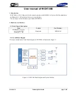
Figure 3
Mounting Bracket Screw Dimensions
N
OTE
Make sure all cables are clear and the bracket sits flush
against the wall / junction box. The joint created with the screws
must have a minimum pullout force of 20 lbs (9 kg).
S
TEP
6
Connect the Ethernet cable and the power cable (optional) to the
access point.
S
TEP
7
With the access point’s LAN1-4 ports facing down and the rear
metal side of the access point facing the bracket, gently slide the
access point onto the bracket. If properly done, the Kensington
lock slot on the AP and the security screw hole on the mounting
bracket will be aligned.
S
TEP
8
Insert the security screw (see
Figure 4
) into the hole on the top of
the access point and tighten it till the screw head is flush with the
access point's body (see
Figure 2
). The security screw is
provided in the Mounting Kit.
Figure 4
Security Screw Dimensions
All dimensions in millimeters (mm).