Reading LED Indicators B-3
Interface Processor LEDs
Interface Processor LEDs
Each interface processor (except the RP, which is not really an interface processor) contains an
enabled LED. When on, this LED indicates that the interface processor is operational and that it is
powered up. It does not necessarily mean that the interface ports are functional or enabled. The
following sections describe the LEDs for each interface processor. The SP has no LEDs other than
the enabled LED to indicate that it is operational.
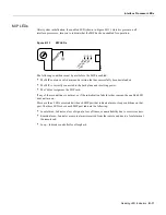
AIP LEDs
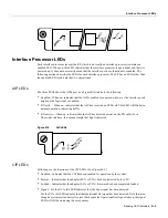
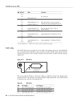
The three LEDs above the ATM port (see Figure B-4) indicate the following:
•
Enabled—When on, indicates that the AIP is enabled for operation; however, the interface ports
might not be functional or enabled.
•
RX cells —When on, indicates that the AIP has received an ATM cell. This LED will flicker in
normal operation, indicating traffic.
•
RX carrier —When on, indicates that the AIP has detected carrier on the RX cable. For a
fiber-optic interface, this means simply that light is detected.
Figure B-4
AIP LEDs
CIP LEDs
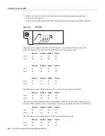
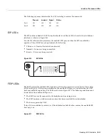
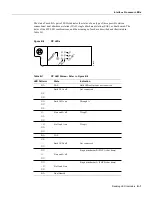
Following are the functions of the CIP LEDs. (See Figure B-5.)
•
Enabled—Indicates that the CIP has been enabled for operation by the system.
•
Present—Indicates that the adapter (ECA or PCA) has been detected by the CIP.
•
Loaded—Indicates that the adapter (ECA or PCA) firmware has been completely loaded.
•
Signal—For the ECA, this LED indicates that the Sync signal has been detected.
For the PCA, this LED indicates that the Operational Out signal has been detected. Note that even
though a system reset and selective reset both cause the Operational Out signal to drop, the signal
LED will still be on during those sequences.
NORMAL
RESET
CPU HALT
H6184
EJECT
SLOT 1
SLOT 0
H2417
ENABLED
RX Carrier
RX Cells
Содержание TelePresence Server 7010
Страница 10: ...x Cisco 7010 Hardware Installation and Maintenence ...
Страница 14: ...iv Cisco 7010 Hardware Installation and Maintenance Document Conventions ...
Страница 112: ...2 52 Cisco 7010 Hardware Installation and Maintenance Initial Configuration Information Page ________ ...
Страница 148: ...3 36 Cisco 7010 Hardware Installation and Maintenance Using the Flash Memory Card ...
Страница 158: ...4 10 Cisco 7010 Hardware Installation and Maintenance Troubleshooting the Processor Subsystem ...
Страница 242: ...5 84 Cisco 7010 Hardware Installation and Maintenance Replacing Internal Components ...
Страница 258: ...A 16 Cisco 7010 Hardware Installation and Maintenance MIP Interface Cable Pinouts ...
Страница 270: ...B 12 Cisco 7010 Hardware Installation and Maintenance Interface Processor LEDs ...
Страница 274: ...C 4 Cisco 7000 Hardware Installation and Maintenance ...
Страница 287: ...Index 13 ...


