background image

8-3

Installation and Upgrade Guide for Cisco Secure Access Control System 5.6

Chapter 8      Installing the Cisco SNS 3415 and Cisco SNS 3495 Hardware Appliances

  Installing the Cisco SNS-3415/3495 Appliance Rack

Step 2

Install the slide rails onto the rack: 

a.

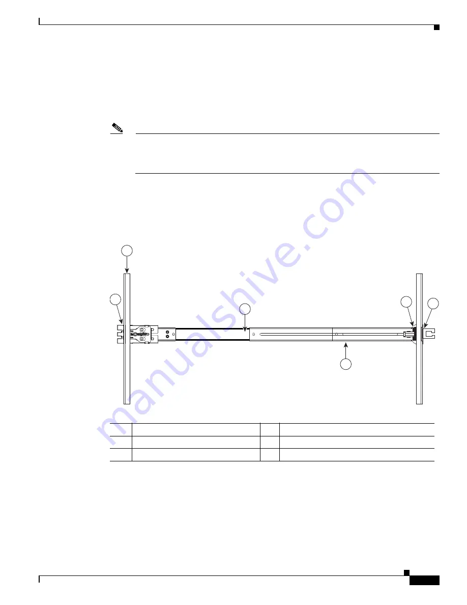
Position a slide-rail assembly inside the two left-side rack posts (see 

Figure 8-2

).

Use the “FRONT” and “REAR” markings on the slide-rail assembly to orient the assembly correctly 
with the front and rear rack posts.

b.

Position the front mounting pegs so that they enter the desired front rack-post holes from the front. 

Note

The mounting pegs that protrude through the rack-post holes are designed to fit round or square 
holes, or smaller #10-32 round holes when the mounting peg is compressed. If your rack has 
#10-32 rack-post holes, align the mounting pegs with the holes and then compress the 
spring-loaded pegs to expose the #10-32 inner peg. 

c.

Expand the length-adjustment bracket until the rear mounting pegs protrude through the desired 
holes in the rear rack post.

Use your finger to hold the rear securing latch open when you insert the rear mounting pegs to their 
holes. When you release the latch, it wraps around the rack post and secures the slide-rail assembly. 

Figure 8-2

Attaching a Slide Rail Assembly

d.

Attach the second slide-rail assembly to the opposite side of the rack. Ensure that the two slide-rail 
assemblies are level and at the same height with each other.

e.

Pull the inner slide rails on each assembly out toward the rack front until they hit the internal stops 
and lock in place. 

Step 3

Insert the server into the slide rails:

33

1689

1

3

2

5

6

4

1

Front-left rack post 

4

Length-adjustment bracket 

2

Front mounting pegs 

5

Rear mounting pegs 

3

Slide-rail assembly 

6

Rear securing latch 

Содержание SNS-3415 series

Страница 1: ...ied personnel should be allowed to install replace or service this equipment Statement 1030 Warning This unit is intended for installation in restricted access areas A restricted access area can be accessed only through the use of a special tool lock and key or other means of security Statement 1017 Installing the Cisco SNS 3415 3495 Appliance Rack This section describes how to install the Cisco S...

Страница 2: ...e steps Step 1 Open the front securing latch see Figure 8 1 The end of the slide rail assembly marked FRONT has a spring loaded securing latch that must be open before you can insert the mounting pegs into the rack post holes a On the rear side of the securing latch assembly hold open the clip marked PULL b Slide the spring loaded securing latch away from the mounting pegs c Release the clip marke...

Страница 3: ...oles align the mounting pegs with the holes and then compress the spring loaded pegs to expose the 10 32 inner peg c Expand the length adjustment bracket until the rear mounting pegs protrude through the desired holes in the rear rack post Use your finger to hold the rear securing latch open when you insert the rear mounting pegs to their holes When you release the latch it wraps around the rack p...

Страница 4: ...the rear of the slide rails Note The CMA is designed for mounting on either the right or left slide rails These instructions describe an installation to the rear of the right slide rails as viewed from the rear of server a Slide the plastic clip on the inner CMA arm over the flange on the mounting bracket that attached to the side of the server See Figure 8 3 Note Whether you are mounting the CMA ...

Страница 5: ...nt Controller 1 4 7a CIMC GUI or CLI interfaces See the user documentation for your firmware release at the following URL http www cisco com en US products ps10739 products_installation_and_configuration_guides_list html Configuring CIMC You can perform all operations on the Cisco SNS 3415 or Cisco SNS 3495 appliance through the CIMC To do this you must first configure an IP address and IP gateway...

Страница 6: ...ccess the CIMC This is the factory default setting along with Active active NIC redundancy and DHCP enabled Cisco Card The ports on an installed Cisco UCS P81E VIC are used to access the CIMC You must select a NIC redundancy and IP setting Note The Cisco Card NIC mode is currently supported only with a Cisco UCS P81E VIC N2XX ACPCI01 that is installed in PCIe slot 1 Step 5 Use this utility to chan...

Страница 7: ...nge of six contiguous MAC addresses Step 7 Optional Use this utility to make VLAN settings Step 8 Use this utility to set a default CIMC user password Note Changes to the settings take effect after approximately 45 seconds Refresh with F5 and wait until the new settings appear before you reboot the server in the next step Step 9 Press F10 to save your settings and reboot the server Note If you cho...

Страница 8: ...415 or Cisco SNS 3495 appliance Ethernet port The Ethernet connector supports Serial over LAN SOL cables The RJ 45 port supports standard straight through and crossover Category 5 unshielded twisted pair UTP cables Cisco does not supply Category 5 UTP cables these cables are available commercially To connect the cable to the appliance Ethernet port Step 1 Verify that the appliance is turned off St...

Страница 9: ... Cisco SNS 3415 or Cisco SNS 3495 appliance includes an EIA TIA 232 asynchronous serial DB 9 connector This serial console connector port allows you to access the appliance locally by connecting a terminal either a PC running terminal emulation software or an ASCII terminal to the console port Table 8 1 Ethernet Cabling Guidelines Type Description 10BASE T EIA Categories 3 4 or 5 UTP 2 or 4 pair u...

Страница 10: ... describes how to connect a keyboard and video monitor to the Cisco SNS 3415 or Cisco SNS 3495 appliance You can connect the keyboard and video monitor to the Cisco SNS 3415 or Cisco SNS 3495 appliance using the KVM connector available in the front panel of the Cisco SNS 3415 or Cisco SNS 3495 appliance A KVM cable is shipped along with the appliance that provides two USB one VGA and one serial co...

Страница 11: ...Server Standalone Mode page 8 11 System BIOS and CIMC Firmware page 8 13 Service Headers and Jumpers page 8 14 Connecting and Powering On the Server Standalone Mode Note This section describes how to power on the server assign an IP address and connect to server management when using the server in standalone mode To use the server in UCS integration specific cabling and settings are required See I...

Страница 12: ...B ports on the rear panel However you cannot use the front panel VGA and the rear panel VGA at the same time If you are connected to one VGA connector and you then connect a video device to the other connector the first VGA connector is disabled Step 3 See the Configuring CIMC section on page 8 5 to enter in to the BIOS CIMC Configuration Utility Use this utility to set NIC mode NIC redundancy and...

Страница 13: ... is 1 4 7a BIOS 1 4 7b 0 LOM LSI storage controller and Cisco UCS P81E VIC firmware to compatible levels See the Cisco Host Upgrade Utility Quick Reference Guide for your firmware level at the documentation roadmap link below Note Your system firmware must be at minimum level 1 2 to use the Cisco Host Upgrade Utility If your firmware is prior to level 1 2 you must use the methods below to update t...

Страница 14: ...tep 5 Press the right arrow key until the Exit menu screen is displayed Step 6 Follow the instructions on the Exit menu screen to save your changes and exit the setup utility or Press F10 You can exit without saving changes by pressing Esc Service Headers and Jumpers This section includes the following topics Header Locations on the Motherboard page 8 14 Using the BIOS Recovery Header J41 page 8 1...

Страница 15: ... hardware If it is a non BootBlock corruption the following message is displayed BIOS FLASH IMAGE CORRUPTED Flash a valid BIOS capsule file using CIMC WebGUI or CLI interface IF CIMC INTERFACE IS NOT AVAILABLE FOLLOW THE STEPS MENTIONED BELOW 1 Connect the USB stick with recovery cap file in root folder 2 Reset the host IF THESE STEPS DO NOT RECOVER THE BIOS 1 Power off the system 2 Mount recovery...

Страница 16: ...ower mode by pressing the Power button on the front panel The server boots with the updated BIOS boot block When the BIOS detects a valid recovery cap file on the USB thumb drive it displays this message recovery cap Step 6 Wait for server to complete the BIOS update then remove the USB thumb drive from the server Note During the BIOS update the CIMC will shut down the server and the screen will b...

Страница 17: ...server Note During the BIOS update the CIMC will shut down the server and the screen will be blank for about 10 minutes Do not unplug the power cords during this update The CIMC will power on the server after the update is complete Step 12 After the server has fully booted power off the server again and disconnect all power cords Step 13 Move the jumper back to the default pins 1 and 2 of the J41 ...

Страница 18: ... when the Power LED on the front panel is amber Step 7 Return the server to main power mode by pressing the Power button on the front panel The server is in main power mode when the Power LED is green Note You must allow the entire server not just the service processor to reboot to main power mode to complete the reset This is because the state of the jumper cannot be determined without the host C...

Отзывы: