3-8
Cisco SFS 3012R Multifabric Server Switch Hardware Installation Guide
OL-11187-01
Chapter 3 Installing and Removing Server Switch Field Replaceable Units (FRUs)
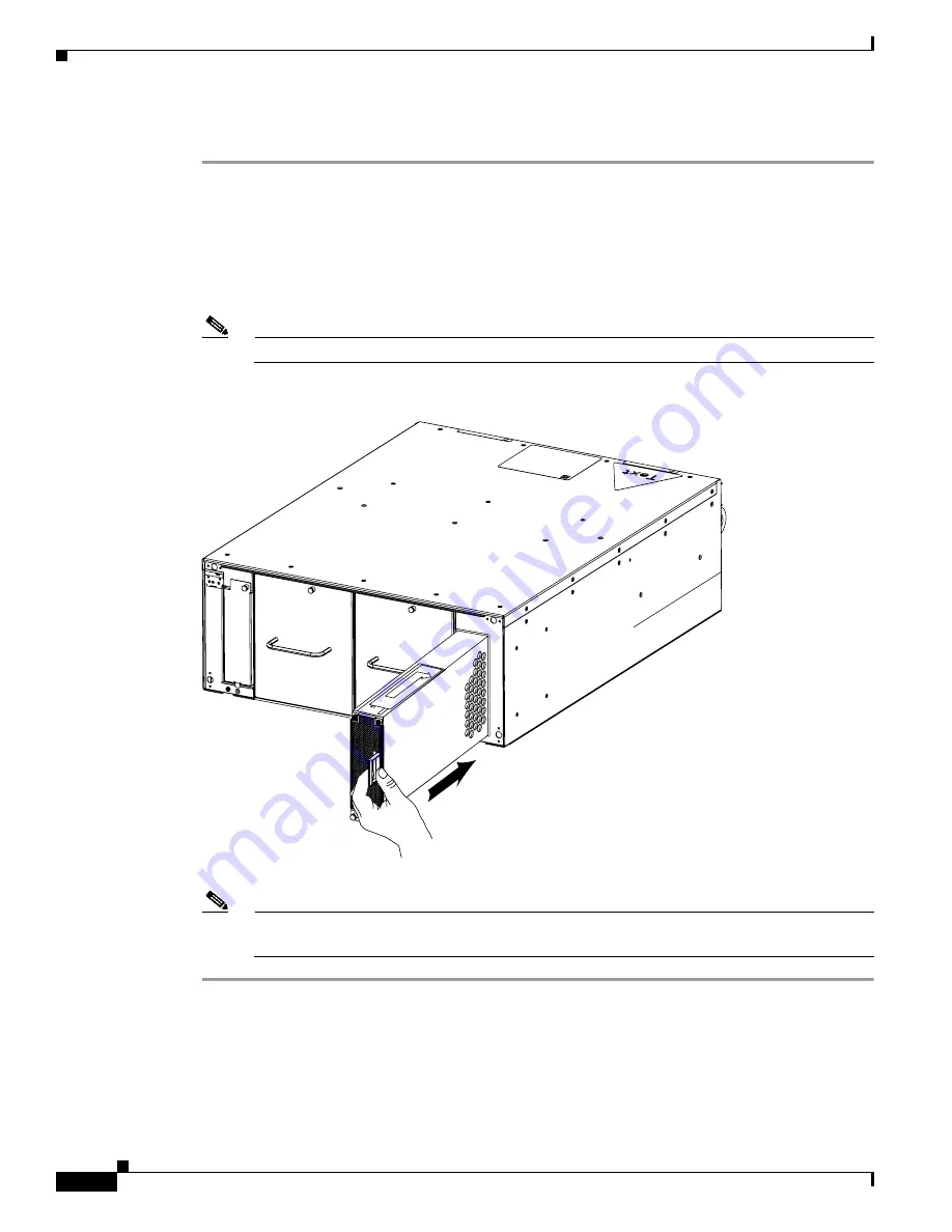
Installing a Power Supply Module
To insert a power supply, perform the following steps:
Step 1
Ground yourself using an approved ground wrist strap.
Step 2
Remove the blanking panel if one resides in the slot.
Step 3
Remove the power supply module from any packaging.
Step 4
Insert the power supply into an open slot such that the pull handle sits toward the outside of the chassis,
away from the blower module. The arrow on top of the power supply or underneath the power supply
must always point to the outside of the chassis.
Note
The power supplies should be inserted in opposite directions of each other.
Step 5
Press the power supply firmly into the chassis.
Note
The power socket on the back (cable end) of the Cisco SFS 3012R Server Switch corresponds to
the power supply module on the same side of the server switch.
180762
Содержание SFS 3012R
Страница 6: ...Contents vi Cisco SFS 3012R Multifabric Server Switch Hardware Installation Guide OL 11187 01 ...
Страница 13: ...xiii Cisco SFS 3012R Multifabric Server Switch Hardware Installation Guide OL 11187 01 Preface Conventions ...
Страница 84: ...Index IN 4 Cisco SFS 3012R Multifabric Server Switch Hardware Installation Guide OL 11187 01 ...


