background image

6-6

Cisco PIX Security Appliance Hardware Installation Guide

78-15170-02

Chapter 6      PIX 525

Installing Failover

VPN Accelerator Card

The VPN Accelerator Card (VAC) for the Cisco PIX security appliance series is a card that provides 
high-performance, tunneling and encryption services suitable for site-to-site and remote access applications. 
The VAC is integrated with PIX 525 unrestricted (UR) and failover (FO) bundles. You can also purchase the 
VAC as a spare for use with PIX 525 units that have a restricted (R) license. 

VPN Accelerator Card+

The VAC+ is a 64-bit/66 MHz PCI card that provides faster tunneling and encryption services for Virtual 
Private Network (VPN) remote access, and site-to-site intranet and extranet applications, than the VAC. 
Each VAC+ occupies a single PCI slot in the system. The VAC+ is supported on any chassis that runs 
software Version 6.3 or later, has an appropriate license to run VPN software, and at least one PCI slot 
available. While the VAC continues to be supported in Version 6.3, if both types of cards, the VAC and 
the VAC+, are installed in a system running Version 6.3, the VAC card is ignored. The VAC+ runs at both 
32-bit/33 MHz and 64-bit/66 MHz, and does not slow down the bus when other 66 MHz cards are 
installed. We strongly recommend that you install the VAC+ in a 64bit/66 MHz slot. Performance will be 
degraded if this recommendation is not followed.

The VAC+ driver supports the following:

3DES, DES, AES, SHA1, MD5 for (IPSec) ESP protocol (For AES, only the CBC mode and key 
sizes of 128, 192, and 256 bits are supported).

SHA1, MD5 for the (IPSec) AH protocol.

Load sharing ESP and AH activity between up to three VAC+.

Diffie-Hellman public key and shared secret generation.

Any other crypto-related activity uses a software implementation.

Installing Failover 

To install a failover connection, perform the following steps:

Step 1

Power off both the primary and secondary units. 

Note

Both PIX security appliances must have the same model number, have at least as much RAM, 
have the same Flash memory size, and be running the same software version. Note that the 
PIX-4FE and PIX-4FE-66 cards are considered equivalent and interchangeable. You can install 
a PIX-4FE in the primary unit and a PIX-4FE-66 in the secondary unit, as long as you install 
them in the same slot number of each chassis. For example, if you install a PIX-4FE in Slot 1 of 
the primary unit, you must also install the PIX-4FE-66 in Slot 1 of the secondary unit.

Step 2

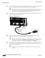
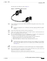
Locate the failover cable (shown in 

Figure 6-6

). This cable is shipped separately from the PIX security 

appliance. The cable is labeled “Primary” on one end and “Secondary” on the other.

Содержание PIX 525

Страница 1: ...e Licenses page 6 5 Installing Failover page 6 6 Installing LAN Based Failover page 6 8 Removing and Replacing the PIX 525 Chassis Cover page 6 9 Replacing a Lithium Battery page 6 12 Installing a Memory Upgrade page 6 12 Installing a Circuit Board in the PIX 525 page 6 15 Installing a DC Power Supply page 6 19 PIX 525 Product Overview Figure 6 1 show the front view of the PIX 525 Figure 6 1 PIX 5...

Страница 2: ... 6 1 lists the state of the PIX 525 front panel LEDs There are three LEDs for the each RJ 45 interface port and three types of fixed interface connectors on the back of the PIX 525 61907 F A I L O V E R 100Mbps ACT 100Mbps ACT LINK LINK 10 100 ETHERNET 1 10 100 ETHERNET 0 USB CONSOLE PIX 525 61913 Table 6 1 PIX 525 Front Panel LEDs LED Color State Description POWER Green On On when the unit has po...

Страница 3: ... unit is going to be installed into an equipment rack a Attach the brackets to the holes near the front of the unit on each side of the PIX 525 using the supplied screws b Attach the unit to the equipment rack F A I L O V E R 100Mbps ACT 100Mbps ACT LINK LINK PIX 525 10 100 ETHERNET 1 10 100 ETHERNET 0 USB CONSOLE 61912 10 100 BaseTX Ethernet 0 RJ 45 10 100 BaseTX Ethernet 1 RJ 45 Console port RJ ...

Страница 4: ...outside network cable to the remaining Ethernet port Refer to the PIX 525 Feature Licenses section on page 6 5 for information on how to configure the ports Note The inside or outside network connections can be made to any available interface port on the PIX 525 If you are only using the ETHERNET 0 and ETHERNET 1 ports connect the inside network cable to the interface connector marked ETHERNET 0 o...

Страница 5: ...IX 525 power on the unit from the switch at the rear of the unit PIX 525 Feature Licenses If you have the PIX 525 UR unrestricted feature license the following options are available If you have a second PIX 525 to use as a failover unit install the failover feature and cable as described in the Installing Failover section on page 6 6 If needed install the PIX security appliance syslog server as de...

Страница 6: ...ther 66 MHz cards are installed We strongly recommend that you install the VAC in a 64bit 66 MHz slot Performance will be degraded if this recommendation is not followed The VAC driver supports the following 3DES DES AES SHA1 MD5 for IPSec ESP protocol For AES only the CBC mode and key sizes of 128 192 and 256 bits are supported SHA1 MD5 for the IPSec AH protocol Load sharing ESP and AH activity b...

Страница 7: ... that is appropriate for your system between the dedicated interfaces on the PIX security appliance Category 5 crossover cable directly connecting the primary unit to the secondary unit 100BaseTX half duplex hub using Straight through Category 5 cables 100BaseTX full duplex on a dedicated switch or dedicated VLAN of a switch Note All enabled interfaces must be connected between the active and stan...

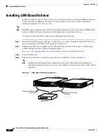
Страница 8: ...nnected to the PIX security appliance disconnect it Step 2 Configure the PIX security appliance for LAN based failover Refer to the chapter on configuring LAN based failover in the configuration guide online at http www cisco com en US docs security pix pix63 configuration guide config html Step 3 Power off both units Step 4 Connect the LAN failover interfaces to the dedicated switch hub as shown ...

Страница 9: ...it fails the secondary unit automatically becomes active Removing and Replacing the PIX 525 Chassis Cover This section describes how to remove and replace the chassis cover from PIX 525 This section includes the following topics Removing the Chassis Cover page 6 9 Replacing the Chassis Cover page 6 11 Removing the Chassis Cover Note Removing the PIX security appliance chassis cover does not affect...

Страница 10: ...moving the Chassis Cover Screws Step 5 Lift the chassis cover upward and pull it away from the tabs on the rear of the chassis See Figure 6 9 Figure 6 9 Removing the Chassis Cover 55324 CISCO SECURITY PIX 525 SE RIES F I R E W A L L PO WER AC TIVE Chassis bottom Front panel Chassis cover 55325 CISCO SECURITY PIX 525 SE RIES F I R E W A L L PO WER AC TIVE ...

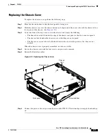
Страница 11: ...owing The chassis cover tabs fit under the edge of the chassis rear panel so that they are not exposed The chassis tabs fit under the chassis cover so that they are not exposed The chassis cover side tabs on both sides fit inside the chassis side panels so that they are not exposed When the chassis cover is properly assembled no tabs are visible Step 4 Secure the chassis cover with the four screws...

Страница 12: ...ement applies to DC models Warning Before performing any of the following procedures ensure that power is removed from the DC circuit To ensure that all power is OFF locate the circuit breaker on the panel board that services the DC circuit switch the circuit breaker to the OFF position and tape the switch handle of the circuit breaker in the OFF position The following statement applies to both AC...

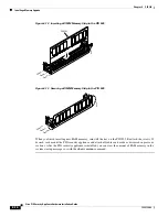
Страница 13: ...sockets Figure 6 11 System Memory Location on the PIX 525 Component Tray Step 6 Locate the wrist grounding strap in the accessory kit and connect one end to the unit or to the PIX security appliance chassis and securely attach the other to your wrist so it contacts your bare skin Step 7 With the wrist strap on your wrist carefully grasp the memory strip from either end Note that a DIMM strip has n...

Страница 14: ...When you finish inserting new RAM memory reinstall the tray on the PIX 525 Reattach the screws If desired rack mount the PIX security appliance and attach all cables and cords as discussed in previous sections After the PIX security appliance is installed you can view the amount of RAM memory in the system startup messages or with the show version command 17997 DIMM B a n k 0 B a n k 2 B a n k 1 1...

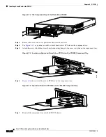
Страница 15: ... circuit board in the PIX 525 perform the following steps Step 1 Locate the grounding strap from the accessory kit Fasten the grounding strap to your wrist so that it contacts your bare skin Attach the other end to bare metal on the PIX 525 chassis Step 2 Remove the screws from the rear panel of the component tray and slide the tray out see Figure 6 14 Table 6 3 PIX 525 Interface Options Restricte...

Страница 16: ...omponent tray Step 5 Attach the screw to hold the circuit board connecting flange to the rear cover plate on the component tray Figure 6 15 Inserting an Expansion Board into a PCI Slot on the PIX 525 Component Tray Step 6 Figure 6 16 shows circuit boards in PCI slots on the component tray Figure 6 16 Expansion Boards in PCI Slots on the PIX 525 Component Tray Step 7 Reinstall the component tray in...

Страница 17: ... a PIX 4FE in the primary unit and a PIX 4FE 66 in the secondary unit as long as you install them in the same slot number of each chassis For example if you install a PIX 4FE in Slot 1 of the primary unit you must also install a PIX 4FE 66 in Slot 1 of the secondary unit The new card has the following characteristics Includes an Intel 21154BE bridge and four Intel 82559 Ethernet MAC PHY devices Su...

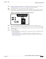
Страница 18: ... VPN Accelerator begins to function immediately after installation without the need of special installation configurations Note The new VPN Accelerator cannot be used with the former PIX security appliance IPSec accelerator in the same chassis The PIX security appliance IPSec accelerator was also known as the Private Link card An illustration of the VPN Accelerator is shown in Figure 6 18 Figure 6...

Страница 19: ...tion Installing a DC Power Supply Warning Before performing any of the following procedures ensure that power is removed from the DC circuit To ensure that all power is OFF locate the circuit breaker on the panel board that services the DC circuit switch the circuit breaker to the OFF position and tape the switch handle of the circuit breaker in the OFF position To install the DC power supply perf...

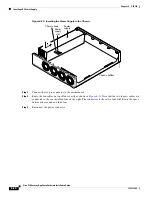
Страница 20: ...he six pin connector to the motherboard Step 4 Route the fan cables on top of fans exactly as shown in Figure 6 21 Note that the two longest cables are connected to the two installed fans on the right The connectors to these two fans will fit into the space between the second and third fans Step 5 Reconnect the power connector 55329 Chassis bottom Power supply Chassis hook Power supply slot ...

Страница 21: ...21 Routing the Fan Cables Step 6 Insert the second fan as shown in Figure 6 21 making sure that the fan cable feeds to your left Position the cables to the two installed fans so that they will fit over the first and second fans Press the fan into place between the four sheet metal tabs 31109 Front panel Sheet metal tabs Base tabs ...

Страница 22: ...re Installation Guide 78 15170 02 Chapter 6 PIX 525 Installing a DC Power Supply Step 7 Reconnect the two pin fan cables to the remaining fan as shown in Figure 6 22 Figure 6 22 Reconnecting the Fan Cables 31910 Fan Fan connector Front panel ...

Страница 23: ... cables feed to the right toward the second fan Route the cable over the fan before you reconnect it When correctly assembled the cables appear as shown in Figure 6 23 Step 9 Starting with the fan farthest away from the power supply bend the cable clamps over wires and into the gap between chassis and fan housing Figure 6 23 Correct Fan Cable Routing 31109 Front panel Sheet metal tabs Base tabs ...

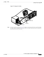
Страница 24: ...e the fan wiring This will make future power supply replacement easier To reroute the fan wiring perform the following steps Step 1 Pull the fan closest to the power supply away from the sheet metal tabs See Figure 6 25 Note To help with reconnecting the cables write down which colored cable connects to which fan See Table 6 4 for a list of the wire colors There are three different lengths of two ...

Страница 25: ...6 PIX 525 Installing a DC Power Supply Figure 6 25 Pulling the Fan Away from the Tabs Step 2 Lift the fan out of the chassis as shown in Figure 6 26 Figure 6 26 Removing the Fan Step 3 Depress the tab as shown in Figure 6 27 55326 Chassis bottom Fan Fan tabs 55327 Chassis bottom Fan ...

Страница 26: ...xt fan and disconnect its cable Step 6 Remove the cables for the two remaining fans Remove the last two fans Step 7 Replace the fans starting with the fan farthest away from the power supply If the bezel is removed make sure the fan farthest away from the power supply does not cover the bezel holes Note Make sure that the label on the fan faces the chassis wall to ensure proper airflow direction S...

Страница 27: ...pplying at least 15 amps A 15 amp circuit breaker is required at the 48 VDC facility power source An easily accessible disconnect device should be incorporated into the facility wiring Step 13 Be sure the PIX 525 power is off by checking the power switch at the rear of the unit Step 14 As shown in Figure 6 29 the PIX 525 is equipped with two grounding studs at the back of the unit which you can us...

Страница 28: ...FF position and tape the switch handle of the circuit breaker in the OFF position Step 16 Strip the ends of the wires for insertion into the power connect lugs on the PIX 525 Step 17 Refer to Figure 6 30 and insert the ground wire into the connector for the earth ground and tighten the screw on the connector Using the same method as for the ground wire connect the negative wire and then the positi...

Страница 29: ...ape from the circuit breaker switch handle and reinstate power by moving the handle of the circuit breaker to the ON position Step 19 Insert the PIX 525 system diskette in the drive at the front of the unit Step 20 Power on the unit from the switch at the rear of the unit If you need to power cycle the DC PIX security appliance wait at least 5 seconds between powering off the unit and powering it ...

Страница 30: ...6 30 Cisco PIX Security Appliance Hardware Installation Guide 78 15170 02 Chapter 6 PIX 525 Installing a DC Power Supply ...

Отзывы: