background image

2-2

Cisco Service Control Engine 1000 2xGBE Quick Start Guide

OL-7822-06

Chapter 2      Rack-Mount the SCE 1000

  Attach the Brackets to the SCE 1000

Figure 2-2

Mounting Bracket for 4-post   Racks

The SCE 1000 mounts to the two front rack posts with brackets that attach to the front of the SCE 1000 
The inside width between the two posts or mounting strips (left and right) must be at least 17.3 inches 
(44 cm).

Note

Remember to leave a two-inch (5 cm) clearance on both sides of the SCE 1000 and at the rear for 
adequate airflow for the inlet and exhaust vents.

Attach the Brackets to the SCE 1000  

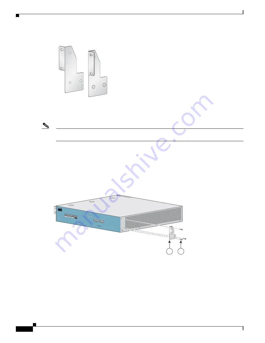
Before installing the SCE 1000 in the rack, you must first install an appropriate rack-mount bracket on 
each side of the front of the SCE 1000, as illustrated in the following figures.

Figure 2-3

Attaching the Mounting Brackets   (4-post)

210430

LINK RX TX

RX

MM

TX

LINK RX TX

RX

MM

TX

PWR B STATU

S

PWR A

BYPASS

10/100/

1000

LINK/

ACTIVE

10/100/

1000

LINK/

ACTIVE

AUX

CONSOLE

MNG 2

MNG 1

Cisco SCE 

1000 

Series

2xGBE

GBE-1

SUB

LINE

NET

1

2

210418

Содержание OL-7822-06

Страница 1: ... West Tasman Drive San Jose CA 95134 1706 USA http www cisco com Tel 408 526 4000 800 553 NETS 6387 Fax 408 527 0883 Cisco Service Control Engine 1000 2xGBE Quick Start Guide Release 3 1 May 2007 Customer Order Number Text Part Number OL 7822 06 ...

Страница 2: ...CISCO OR ITS SUPPLIERS HAVE BEEN ADVISED OF THE POSSIBILITY OF SUCH DAMAGES Any Internet Protocol IP addresses used in this document are not intended to be actual addresses Any examples command display output and figures included in the document are shown for illustrative purposes only Any use of actual IP addresses in illustrative content is unintentional and coincidental Cisco Service Control En...

Страница 3: ... Assemble the Crossrail Supports 2 3 Attach the Crossrail Supports to the Rack 2 4 Mount the System to the Rack 2 4 C H A P T E R 3 Connect the Power Supply Units 3 1 Connect the Chassis Ground 3 1 Connecting the Power 3 2 Connect the DC Input Power Supply Unit 3 3 Connect the AC Input Power Supply Unit 3 4 C H A P T E R 4 Connect the Management Interfaces and Perform Initial System Configuration ...

Страница 4: ...gy Dependent Parameters 4 20 Examples 4 21 Step 10 Completing and Saving the Configuration 4 22 Examples 4 24 Connect the Management Interface 4 25 EXAMPLE 4 25 C H A P T E R 5 Cable the Line Ports 5 1 Information About Cabling 5 1 Single Link Inline Topology 5 1 Single Link Receive only Topology 5 2 Cabling the Line Interfaces 5 3 Configure GigabitEthernet Auto Negotiation 5 3 Connect the GBE Lin...

Страница 5: ...E R 7 Installing a Service Control Application 7 1 Advanced Configuration of the SCE Platform 7 1 Loading and Activating a Service Control Application 7 1 C H A P T E R 8 Troubleshoot Startup Problems 9 1 SCE 1000 Operational Status 9 1 Identifying Startup Problems 9 3 CLI Commands for Troubleshooting 9 3 ...

Страница 6: ...Contents vi Cisco Service Control Engine 1000 2xGBE Quick Start Guide OL 7822 06 ...

Страница 7: ...cted access area is where access can only be gained by service personnel through the use of a special tool lock and key or other means of security and is controlled by the authority responsible for the location Voltage is present on the backplane when the system is operating To reduce risk of an electric shock keep hands and fingers out of the power supply bays and backplane areas Do not work on t...

Страница 8: ...ads DC power only Ring terminals must be UL approved and suitable for 12 AWG wire AC power cords AC power only shipped with SCE 1000 Rack mounting kit shipped with SCE 1000 Spare screws for changing bracket position Prepare for Rack Mount Installation Before you begin the rack mounting tasks determine the type of rack four post or two post that you will be using Workbench or Tabletop Installation ...

Страница 9: ...ists for the SCE 1000 platform The SCE 1000 platform has at least 2 inches 5 cm of clearance at each side and at least 5 inches 12 7 cm of clearance at the rear to allow proper air flow Step 1 Remove the adhesive strips from the four rubber feet and affix the feet onto the four marked locations on the bottom panel of the unit Step 2 Place the SCE 1000 platform on the tabletop or workbench ...

Страница 10: ...1 4 Cisco Service Control Engine 1000 2xGBE Quick Start Guide OL 7822 06 Chapter 1 Prepare for Installation Workbench or Tabletop Installation ...

Страница 11: ... only Mount the System to the Rack The SCE 1000 Mounting Brackets There are two standard types of equipment racks and the appropriate brackets for each are provided in the enclosed kit 19 rack with front rack posts the mounting kit includes two mounting brackets as illustrated below Figure 2 1 Mounting Bracket for 2 post Racks 19 rack with front and back rack posts in addition to the mounting brac...

Страница 12: ...mber to leave a two inch 5 cm clearance on both sides of the SCE 1000 and at the rear for adequate airflow for the inlet and exhaust vents Attach the Brackets to the SCE 1000 Before installing the SCE 1000 in the rack you must first install an appropriate rack mount bracket on each side of the front of the SCE 1000 as illustrated in the following figures Figure 2 3 Attaching the Mounting Brackets ...

Страница 13: ...ck with only two posts skip to Mount the System to the Rack If mounting the SCE 1000 in a rack with four posts proceed to the next step Installing the Crossrail Supports Four post rack only Installing the Crossrail Supports Four post rack only This section provides information for assembling the crossrail supports and attaching them to the rack When mounting in a rack with four posts front and bac...

Страница 14: ...ts with the side of the rack parallel to the floor Figure 2 6 Attaching the Crossrails to the Rack Step 2 Insert and tighten two screws to the front posts or mounting strips of the rack Step 3 Insert and tighten two screws to the Back posts of the rack Step 4 Repeat steps 2 and 3 on the other side of the rack keeping the brackets flush against the posts and parallel to the supporting bracket on fi...

Страница 15: ...te screws to the rack DETAILED STEPS Step 1 Make sure that the rack brakes are locked or that the rack is otherwise stabilized Figure 2 7 Sliding the SCE Platform into the Rack Step 2 Position the SCE 1000 so that the front end is closest to you and lift it carefully to place it into the rack To prevent injury avoid sudden twists or moves Step 3 Slide the SCE 1000 into the rack pushing it back unt...

Страница 16: ...s align the holes in the brackets with the holes on the rack or mounting strip Figure 2 8 Securing the SCE Platform to the Rack Step 5 For each bracket insert and tighten two appropriate screws to the rack Note Since the brackets support the weight of the entire SCE 1000 chassis be sure to use all four screws to fasten the two rack mount brackets to the rack posts LINK RX TX RX MM TX LINK RX TX RX...

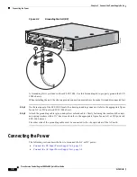
Страница 17: ...er Supply Units This section provides information for grounding the SCE 1000 platform and connecting the AC or DC power supply units Connect the Chassis Ground page 3 1 Connecting the Power page 3 2 Connect the Chassis Ground Figure 3 1 Grounding the Unit AC IN POWER B OK IN POWER A OK BYPASS 1 210421 2 1 ...

Страница 18: ...assis grounding connector refer to the appropriate figure for an AC or DC powered SCE 1000 above Step 2 Attach the grounding cable green and yellow colored cable firmly fastening the enclosed hex nuts and spring washers with a hex wrench refer to the appropriate figure for an AC or DC powered SCE 1000 above The other side of the grounding cable must be connected to the site equivalent of the AC ea...

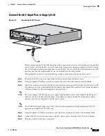
Страница 19: ...ewdriver remove the protective plate from the terminal block Step 3 Insert one receptacle screw into the hex or loop connector on one power line input insert the screw with the connector into the corresponding lead receptacle and tighten the receptacle screw using the number 2 Phillips Repeat for the remaining power line input lead Note The color coding of the DC input power supply leads depends o...

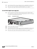
Страница 20: ...r cable into the AC input power receptacle on the AC input power supply For AC input power we recommend powering the SCE 2000 platform from a 120 VAC 15A receptacle U S 240 VAC 10A international at the power source Figure 3 4 Connecting the AC Power Step 2 Plug the AC power supply cable into the AC power source Step 3 Turn the on off switch to the on position Step 4 Look at the IN and OK LEDs on t...

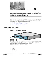
Страница 21: ...ge 4 2 Connect the Management Interface page 4 25 Connect the Local Console Figure 4 1 Connecting to the Local Console You must first connect the unit to a local console and configure the initial settings for the SCE 1000 to support remote management When the initial connection is established the setup utility will run automatically prompting you to perform the initial system configuration Make su...

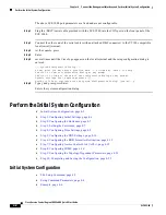
Страница 22: ...rl C to abort configuration dialog at any prompt Use ctrl Z to jump to the end of the configuration dialog at any prompt Default settings are in square brackets Would you like to continue with the System Configuration Dialog yes no y Step 5 Type y and press press Enter Enters the system configuration dialog Perform the Initial System Configuration Initial System Configuration page 4 2 Step 1 Confi...

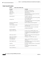
Страница 23: ...er values When the dialog is complete you may review the new configuration before applying it The system displays the configuration including parameters that were not changed The system also displays any errors that are detected in the configuration When the configuration is satisfactory you may apply and save the new configuration The following table lists all the parameters included in the initi...

Страница 24: ...ion status Enable or disable password encryption Time Settings time zone name and offset Standard time zone abbreviation and minutes offset from UTC local time and date Current local time and date Use the format 00 00 00 1 January 2002 SNTP Configuration broadcast client status Set the status of the SNTP broadcast client If enabled the SCE will synchronize its local time with updates received from...

Страница 25: ...s to allow GET access and associated ACLs maximum 20 SET community names Community strings to allow SET access and associated ACLs maximum 20 trap managers maximum 20 Trap manager IP address community string and SNMP version Authentication Failure trap status Sets the status of the Authentication Failure traps enterprise traps status Sets the status of the enterprise traps system administrator Nam...

Страница 26: ...fault values for the parameters within the menu Each group of related parameters is prefaced by a question asking whether you want to enter the menu To skip the menu answer no n to the question Example Would you like to enter the SNMP configuration menu n To abort the setup dialog at any point without making any configuration changes press c All changes already entered will be lost with the except...

Страница 27: ...000 It appears as part of the CLI prompt and is also returned as the value of the MIB II object sysName The maximum length is 20 characters The default hostname is SCE 1000 Step 1 Specify the hostname for the SCE platform The default hostname is displayed To accept the displayed value press press Enter To change the value type any desired character string and press press Enter Enter hostname SCE 1...

Страница 28: ... type the desired string and press press Enter Step 3 Configure the Root password The default Root password is displayed To accept the displayed value press press Enter To change the value type the desired string and press press Enter Step 4 Configure password encryption By default password encryption is not enabled To disable password encryption press Enter To enable password encryption type y an...

Страница 29: ...ike to enter the Time settings menu no y Type y and press press Enter Step 2 Configure the time zone name Type the time zone abbreviation and press press Enter Enter time zone name UTC CET Step 3 Specify the offset from UTC Type the minutes offset from UTC and press press Enter Enter time zone minutes offset from UTC 60 Step 4 Confirm the local time and date The local time and date are displayed a...

Страница 30: ...e time setting dialog In addition to setting the time zone time and date are changed and SNTP unicast updates are configured Would you like to enter the Time settings menu no y Enter time zone name UTC ISR Enter time zone minutes offset from UTC 120 The local time and date is 15 35 23 ISR FRI July 19 2002 Would you like to set a new time and date no y This change will take effect immediately both ...

Страница 31: ...disabled Step 3 Type the default domain name to be used and press press Enter Note that there is no default domain name You may accept the default domain name or enter a new one Enter default domain name Step 4 Configure the primary domain name server Type the IP address of the primary domain name server and press press Enter Enter Primary DNS IP address Note that there is no default for this para...

Страница 32: ... Enter The RDR formatter destination dialog begins Step 2 Specify the IP address of the RDR formatter destination Type the IP address of the RDR formatter destination and press press Enter Enter RDR formatter destination s IP address Note that there is no default for this parameter Step 3 Specify the TCP port number of the RDR formatter destination Type the TCP port number of the RDR formatter des...

Страница 33: ...IP address in the desired range then enter the wildcard bits that define the range This wildcard functions like a reverse mask in that all 1 bits in the wildcard indicate the corresponding bit in the IP address should be ignored All other bits must match the corresponding bit in the specified IP address Refer to the table below for examples Each range of IP addresses can be configured to be permit...

Страница 34: ...n ACL is 20 8 When all entries are added to one list you are asked whether you would like to create another ACL You may define up to 99 ACLs 9 Restrict IP access to the SCE 1000 by assigning the appropriate ACL 10 Restrict Telnet access to the SCE 1000 by assigning the appropriate ACL DETAILED STEPS Step 1 Enter the Access Control Lists configuration menu Would you like to enter the Access lists c...

Страница 35: ...reate another ACL type y and press Enter Would you like to configure another list no y Enter up to 20 IP addresses in this new ACL as described in step 5 and step 6 When all ACLs have been created press press Enter Would you like to configure another list no You are now prompted to assign the desired ACLs to restrict IP and Telnet access Step 9 Restrict IP access to the SCE 1000 by assigning the a...

Страница 36: ...other entry to this list no y Does this entry permit access yes n Enter IP address or the word any to denote any IP address any This entry matches every IP address no use in adding more entries to this list Would you like to configure another list no Enter IP access class 0 1 Enter Telnet access class 0 2 EXAMPLE 2 This example skips the first section of the dialog creating modifying and proceeds ...

Страница 37: ...nity string 21 Configure the trap manager SNMP version 22 Configure additional trap managers 23 To add more entries do not accept the default 24 Enter up to 20 trap managers as described in step 7 25 When all entries have been added accept the default 26 Configure the Authentication Failure trap status 27 Configure the SCE enterprise trap status 28 Specify the system administrator DETAILED STEPS S...

Страница 38: ...ill respond only to SET requests that use this community string Enter SNMP SET community name Note that there is no default for this parameter b Assign an access list to restrict the SNMP management stations that may use this SET community Type a number 1 through 99 or type 0 to permit access to all IP addresses and press press Enter Enter Access list number allowing access with this community str...

Страница 39: ...ter to accept Step 9 Configure the Authentication Failure trap status To disable the Authentication Failure trap press press Enter To enable the Authentication Failure trap type y and press press Enter Enable the Authentication Failure trap no Step 10 Configure the SCE enterprise trap status To disable the SCE enterprise traps type n press press Enter To enable the SCE enterprise traps type y and ...

Страница 40: ...red manner There are three topology related parameters Connection mode Can be either Inline or Receive only depending on the physical installation of the SCE 1000 Bypass state when the SCE 1000 is not operational on failure This parameter determines whether the system cuts the traffic or bypasses it when the SCE 1000 has failed Status after reboot caused by fatal error or abnormal shutdown This pa...

Страница 41: ...parameters for each topology EXAMPLE 1 page 4 21 EXAMPLE 2 page 4 21 EXAMPLE 3 page 4 22 EXAMPLE 1 Following is a sample topology configuration for a topology using an external switch All other parameter values are automatically assigned by the system as follows Link bypass mode on failure Bypass Admin status of the SCE after abnormal boot Operational Would you like to enter the Topology configura...

Страница 42: ...in status after abnormal reboot is Operational Would you like to enter the Topology configuration menu no y Enter Connection mode 1 inline 2 receive only Enter your choice 1 2 Enter On failure behavior 1 Bypass 2 Cutoff Enter your choice 1 2 Enter admin status of the SCE after abnormal boot 1 Operational 2 Not Operational Enter your choice 1 Data collection for the system configuration is complete...

Страница 43: ...is ended Step 4 Confirm saving and applying the configuration If there are no errors the system requests confirmation of either a yes or no answer to prevent mistakes Type the appropriate answer y or n and press press Enter The running configuration would be overwritten by the changes you have just entered are you sure yes no The selected action is carried out by the system The selected action is ...

Страница 44: ... 2 permits all addresses while Access list 1 denies it Apply and Save this configuration yes no n Setup procedure aborted no configuration changes made EXAMPLE 2 Following is an example of a configuration that was applied and saved to the startup configuration as well as to an FTP site Although not demonstrated in this example it is recommended that you always view the configuration before applyin...

Страница 45: ...ement network The Link LED on the SCE 1000 management port should light up Step 3 Test connectivity From the host that you intend to use for remote management ping to the SCE 1000 by typing ping and the SCE 1000 IP address and pressing Enter see the example below This verifies that an active connection exists between the specified station and the management port EXAMPLE The following example displ...

Страница 46: ...4 26 Cisco Service Control Engine 1000 2xGBE Quick Start Guide OL 7822 06 Chapter 4 Connect the Management Interfaces and Perform Initial System Configuration Connect the Management Interface ...

Страница 47: ...age 5 3 Information About Cabling Single Link Inline Topology page 5 1 Single Link Receive only Topology page 5 2 Single Link Inline Topology In the inline or bump in the wire topology illustrated in the diagram bellow the SCE 1000 resides physically on the data link between the subscriber side usually either a BRAS in DSL access a PDSN in wireless access a CMTS in the Cable access or a switch or ...

Страница 48: ... only In this topology the traffic passes through the external splitter which splits traffic to the SCE 1000 The SCE 1000 therefore is in receive only topology having only traffic monitoring capabilities Note Receive only topologies can also be implemented using a switch Such a switch must support SPAN functionality that includes separation between ingress and egress traffic and multiple SPAN port...

Страница 49: ...startup config and press Enter Step 1 At the SCE 1000 prompt type configure and press press Enter Enters Global Configuration Mode Step 2 At the SCE 1000 config prompt type interface GigabitEthernet 0 portnumber and press press Enter Enters the GigabitEthernet Interface configuration mode for the specified GBE port portnumber is the number of the selected port 1 or 2 Step 3 At the SCE 1000 config ...

Страница 50: ...ers The transceiver type is indicated on the front panel under the ports Note that both transceivers on any individual SCE 1000 are the same either 850nm Multimode OR 1310 Single Mode Step 1 Plug the specified fiber optic cable see table above into the appropriate GBE port on the front panel of the SCE 1000 Step 2 Verify that the link LED is green Cisco SCE 1000 Series 2xGBE LINK RX TX RX MM TX LI...

Страница 51: ...ol Engine 1000 2xGBE Quick Start Guide OL 7822 06 Chapter 5 Cable the Line Ports Cabling the Line Interfaces If the link LED does not light try removing the network cable plug and reinserting it firmly into the module socket ...

Страница 52: ...5 6 Cisco Service Control Engine 1000 2xGBE Quick Start Guide OL 7822 06 Chapter 5 Cable the Line Ports Cabling the Line Interfaces ...

Страница 53: ...hat in an inline topology the Rx and Tx LEDs indicate that packets are being received transmitted by the SCE 1000 platform In optical splitter topologies the Rx LEDs are the sole indicators The Tx LEDs do not blink since the Tx is not connected to the port in this topology Final Tests The procedures for performing the final tests to verify that the SCE 1000 is functioning properly are explained in...

Страница 54: ...ompt type show logger device User File Log counters and press press Enter EXAMPLE The following example shows the current User File Log device counters SCE 1000numbershow logger device user file log counters Logger device User File Log counters Total info messages 1 Total warning messages 0 Total error messages 0 Total fatal messages 0 If there are Total error messages or Total fatal messages use ...

Страница 55: ...ne vty 0 4 no timeout exit SCE 1000number Saving the Configuration Settings When you make changes to the current running configuration and you want those changes to continue to be valid when the system restarts you must save the changes before leaving the management session that is you must save the running configuration to the startup configuration file The SCE platform provides multiple interfac...

Страница 56: ...ps version 1 public interface LineCard 0 connection mode active no silent no shutdown flow aging default timeout UDP 60 interface FastEthernet 0 0 ip address 10 1 5 109 255 255 0 0 interface FastEthernet 0 1 interface FastEthernet 0 2 exit line vty 0 4 no timeout exit SCE 1000 SCE 1000 copy running config startup config Writing general configuration file to temporary location Backing up general co...

Страница 57: ...guration refer to the following documents Cisco Service Control Engine SCE Software Configuration Guide Cisco Service Control Engine SCE CLI Command Reference Loading and Activating a Service Control Application The SCE 1000 platform provides the basic functionalities of Service Control analysis and enforcement A Service Control solution requires that a Service Control application be loaded into t...

Страница 58: ...7 2 Cisco Service Control Engine 1000 2xGBE Quick Start Guide OL 7822 06 Chapter 7 Installing a Service Control Application Loading and Activating a Service Control Application ...

Страница 59: ...e SCE 1000 The Status LED on the SCE 1000 Front Panel reflects the current SCE 1000 operational status The operational status can be displayed using CLI command show system operation status Table 8 1 SCE 1000 Operational States SCE 1000 Operational Status Description Status LED State Booting Initial state after reset Orange Operational SCE 1000 becomes operational after completing the following pr...

Страница 60: ...at caused the SCE 1000 to be in Warning state is resolved for example link is up the SCE 1000 reverts to Operational state Flashing orange Failure System is in Failure state after Boot due to one of the following conditions Power on test failure Three abnormal reboots in less than 20 minutes Platform configured to enter Failure mode consequent to failure induced reboot this is configurable using C...

Страница 61: ...ted to the console port If the banner is displayed but the Status LED is flashing orange indicating a warning state check the user log At the prompt type more user log If any of the following warning messages appear turn the SCE 1000 platform off and call technical support voltage problem fans problem abnormal raise in interior temperature If the following warning message appears delete unneeded f...

Страница 62: ...mmand Standard IP access list 1 Permit 10 1 1 0 wildcard bits 0 0 0 255 deny any show telnet Displays the status of the telnet server daemon status or any active Telnet sessions sessions Following is a sample output from the show telnet command show telnet sessions There is 1 active telnet session Index Source 0 10 1 1 201 show telnet status Telnet deamon is enabled show line vty timeout Shows the...

Страница 63: ...ick Start Guide OL 7822 06 Chapter 8 Troubleshoot Startup Problems CLI Commands for Troubleshooting Out unicast packets 0 Out non unicast packets 0 Out packets discarded 0 Refer to The User Log for an explanation of commands related to the user log ...

Страница 64: ...8 6 Cisco Service Control Engine 1000 2xGBE Quick Start Guide OL 7822 06 Chapter 8 Troubleshoot Startup Problems CLI Commands for Troubleshooting ...

Отзывы: