7-18
Cisco MGX 8220 Installation and Configuration
Release 5.0, Part Number 78-6430-03 Rev. D0, November 2003
Chapter
Connecting Power for AC Systems
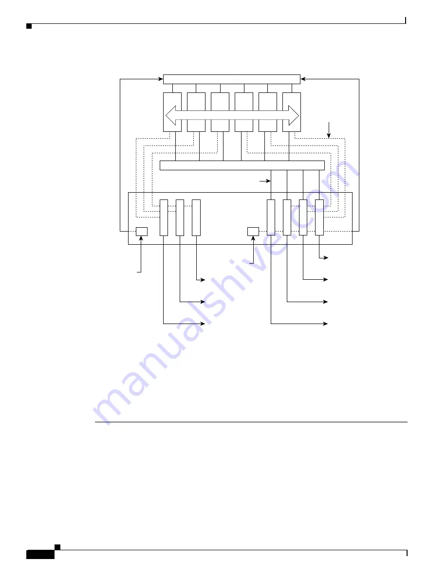
Figure 7-13 AC Power Assembly Block Diagram
Each of the right three connectors of the group of four also provides a power supply status signal for
monitoring power supply performance by an MGX 8220 shelf. Each of these connectors provides a
status signal for a particular power supply as shown in the diagram.
The group of three connectors on the left of the rear panel supplies status signals for any remaining
power supplies that are configured in the assembly.
Perform the following steps to connect the power supplies. (See Figure 7-14 and Figure 7-15.)
Step 1
For each shelf, connect one end of a cable to one of the right connectors, and one end of another cable
to one of the left connectors.
Using the special cables supplied with the power assembly, use one or two cables for each shelf. Each
shelf should use one cable from the right connectors and optionally one cable from the left connectors.
Step 2
Insert each of the two cables into one of the power entry apertures on the shelf and secure with the
provided screws.
The other end of the cable has a connector and a fixture for attaching to the power entry aperture on the
rear of the shelf. The cable from the left side of the power assembly is connected to the left power entry
connector in the MGX 8220 shelf. Likewise, the cable from the right side of the power assembly is
connected to the right power entry connector in the MGX 8220 shelf.
Power
Status
signals
Power and monitoring
for PS#1
Power and monitoring
for PS#2
Power and monitoring
for PS#3
Power
Monitoring for PS#4
Monitoring for PS#5
Monitoring for PS#6
Optional
secondary
AC power input
Rear panel
Up to 6 power supplies
6 5 4 3 2 1
Primary AC
power input
H10026


