background image

Upgrading the Flash EPROM Memory Card  7

Replacing Boot ROMs

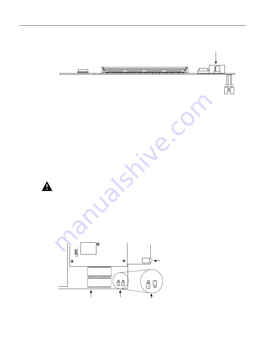
Figure 4

Flash EPROM Card and Connector—Side View

To reinstall the Flash EPROM card, see the section “Replacing Boot ROMs.”

Replacing Boot ROMs

If your Cisco 4000 router does not have boot ROMs more recent than Cisco Internetwork Operating
System (Cisco IOS) Release 10.2(8), you will need to upgrade them with the boot ROMs provided
with the Flash EPROM card. To upgrade the boot read-only memory (ROM) software to a new
software image, the existing boot ROMs must be replaced.

Step 1

Open the chassis and expose the boot ROMs following the procedures in the section
“Accessing the Internal Components of the Router.”

Step 2

After the boot ROMs (FW1 and FW2) on the system card are exposed (see Figure 5),
follow the procedures in this section to replace the ROMs.

Caution

The correct placement of the boot ROMs is crucial. If improperly positioned, the new

components could be damaged when the system is powered on. Read through all of the instructions
before proceeding. To prevent damage to the ROMs from ESD (when handling the system and its
components), follow the ESD procedures described earlier. Also, be careful not to damage or scratch
the printed circuit card under the ROMs.

Step 3

Locate the boot ROMs, FW1 and FW2. (See Figure 5.)

Figure 5

Boot ROMs Locations and Boot ROMs Capacity Jumpers

Step 4

Using an EPROM extraction tool or a small flat-blade screwdriver, gently remove the boot
ROMs and set them aside.

96-pin connector

Software update jumpers

H4466

FW1

FW2

Boot ROMs

LED

H4465

SOFTWARE UPDATE

ALLOWED

INHIBITED

W1

J5 J6 

J5 J6 

8 MB boot ROMs 

4  MB boot ROMs 

Содержание MEM-NP16F Series

Страница 1: ...Kit The Flash EPROM memory card upgrade kit includes the following components An updated Flash EPROM memory card that supports 8 or 16 MB of Flash memory Updated boot ROMs that provide support for the new Flash EPROM memory card Safety Recommendations Warning To ensure your safety and the safety of others be sure the power is OFF and the power cord is unplugged before working on the router Caution...

Страница 2: ...minals Follow these guidelines when working on equipment powered by electricity Locate the emergency power off switch in the room in which you are working Then if an electrical accident occurs you can quickly shut the power OFF Before working on the system turn OFF the power and unplug the power cord Disconnect all power before doing the following Installing or removing a router chassis Working ne...

Страница 3: ...r 1 and Number 2 Phillips ROM extraction tool or flat bladed screwdriver Accessing the Internal Components of the Router To access the internal components of the router you must remove the component tray Warning Hazardous voltages may exist in or near the power supply so use extreme caution when working near the power supply Before starting any of these procedures turn OFF power to the system unpl...

Страница 4: ...erneath either on your work surface or with your hands to prevent personal injury See Figure 1 Figure 1 Component Tray Removal for Chassis With a Safety Latch Step 6 While supporting the component tray with one hand push down on the safety latch tab while pulling out on the component tray Step 7 Set the component tray on your work surface Removing the Component Tray from a Chassis without a Safety...

Страница 5: ...re 2 Component Tray Removal for Chassis Without a Safety Latch Warning Support the component tray from underneath either on your work surface or with your hands to prevent personal injury See the hand in Figure 2 Step 5 While facing the chassis rear panel pull the handle on the right side of the router while supporting the component tray with one hand Slide the component tray out of the chassis sh...

Страница 6: ...event damaging the Flash EPROM card handle it by the sides only Step 3 Holding the Flash EPROM card by its edges pull straight up to lift the card out of its connector See Figure 4 The system memory SIMMs will now be exposed FW1 FW2 EPROM card cutaway view 96 pin EPROM connector EPROM card mounting screw LEDs Boot ROMs Module mounting screws Token Ring module Dual serial module Ethernet module EPR...

Страница 7: ...2 on the system card are exposed see Figure 5 follow the procedures in this section to replace the ROMs Caution The correct placement of the boot ROMs is crucial If improperly positioned the new components could be damaged when the system is powered on Read through all of the instructions before proceeding To prevent damage to the ROMs from ESD when handling the system and its components follow th...

Страница 8: ...ap ensuring that it makes good skin contact Connect the equipment end of the wrist strap to the metal back plate of the chassis avoiding contact with the connectors Step 2 Line up the Flash EPROM card with the 96 pin connector see Figure 4 and screw holes Step 3 Holding the Flash EPROM card by its edges push straight down on the connector see Figure 4 to insert its connector into the socket on the...

Страница 9: ...ity none stop bits 1 and baud rates up to 14 4 kbps For a copy of CIO s Frequently Asked Questions FAQ contact cio help cisco com For additional information contact cio team cisco com Note If you are a network administrator and need personal technical assistance with a Cisco product that is under warranty or covered by a maintenance contract contact Cisco s Technical Assistance Center TAC at 800 5...

Страница 10: ...10 Upgrading the Flash EPROM Memory Card Cisco Information Online ...

Отзывы: