8 Upgrading DRAM on the CIP2
Upgrading DRAM on the CIP2
Installing a CIP2
Follow these steps to install the CIP2 in the router:
Step 1
Attach an ESD-preventive wrist strap between you and the chassis.
Step 2
Hold the CIP2 handle with one hand and placing your other hand under the carrier to
support the CIP2, guide it into the slot. Avoid touching the motherboard, adapters, or pins.
Step 3
Place the back of the CIP2 in the slot and align the notches along the edges of the carrier
with the grooves in the slot. (See Figure 3a on page 5.)
Step 4
Keep the carrier parallel to the backplane and carefully slide the CIP2 into the slot until
the back of the faceplate touches the ejector levers, then stop. (See Figure 3b on page 5.)
Caution
Always use the ejector levers when installing or removing interface processor modules. A
module that is partially seated in the backplane will cause the system to halt and subsequently crash,
and shoving or slamming the interface processor into the slot can damage the backplane and pins.
Step 5
Using the thumb and forefinger of each hand to pinch each ejector lever, simultaneously
push both ejector levers inward (toward the interface ports) until they snap into place and
are parallel to the faceplate. (See Figure 3c on page 5.)
Step 6
Use a screwdriver to tighten the two captive screws on the interface processor faceplate.
(See Figure 3a on page 5.) This prevents the interface processor from becoming partially
dislodged from the backplane and ensures proper EMI shielding. (These screws must be
tightened to meet EMI specifications.)
Step 7
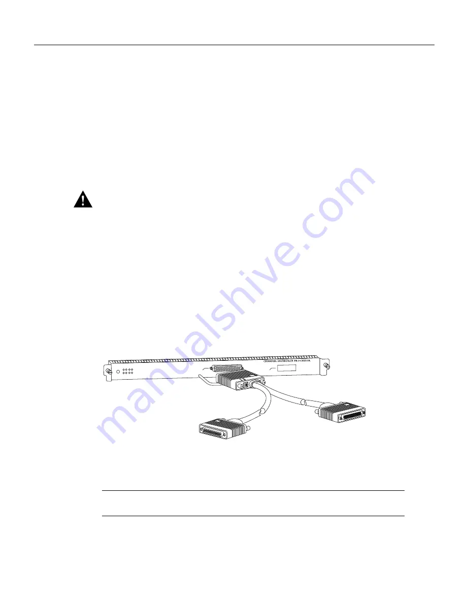
If you have a PCA, reattach the PCA connector of the Y cable. (See Figure 6.)
Figure 6
Attaching the Y Cable to the PCA Connector—V-Type Cables Not Shown
Note
If there are only ECAs attached to your CIP2, proceed to the section “Attaching the ESCON
Cable to the Host Channel” on page 10.
0
Single PCA
1
H2450
PCA connector
From host or mainframe
(male, dark gray or black)
To next control
unit or terminator
(female, light gray)


