Upgrading DRAM on the CIP2 3
Upgrading DRAM on the CIP2
Upgrading DRAM on the CIP2
This section includes procedures to perform an upgrade of DRAM SIMMS on the CIP2. DRAM
SIMMs must be removed or installed in the field by a Cisco-certified maintenance provider only.
Caution
Improper handling of the bus and tag and ESCON channel cables and interface adapters
can cause significant problems for other devices on the same channel as the CIP2. Mainframe
processors can, in some circumstances, be rendered inoperable due to system crashes caused by
improper cable handling. We strongly recommend that only Cisco-certified maintenance providers
connect and disconnect channel cables between the router and the mainframe, and perform
maintenance procedures on the CIP2.
The procedures in this section include the following:
•
Removing a CIP2, page 3
•
Removing and Replacing DRAM SIMMs, page 6
•
Installing a CIP2, page 8
•
Attaching the ESCON Cable to the Host Channel, page 10
Removing a CIP2
Follow these steps to remove a CIP2:
Step 1
Attach an ESD-preventive wrist strap between you and the chassis.
Step 2
If you have a Parallel Channel Adapter (PCA), vary offline the addresses assigned to the
CIP2. For instructions on how to vary offline, refer to your operating system’s
documentation.
Step 3
Shut down the interfaces on the CIP2 using the shutdown command. For the ESCON
interface on ESCON Channel Adapter (ECA), this will prevent logouts from occurring
on the router console when the optical-fiber cable is removed.
Step 4
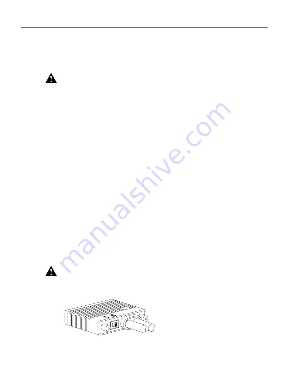
The select/bypass switch marked S (for select mode) and B (for bypass mode) is located
on the rear of the PCA connector. (See Figure 7.) The select/bypass switch is required to
allow the cable to be separated from the PCA without “opening” the select-out loop. If
you have a PCA, place the select/bypass switch in bypass mode. (See Figure 1.)
Caution
To prevent halting or otherwise affecting the mainframe operating system, verify that the
select/bypass switch is in bypass mode before you remove the PCA connector from the CIP2.
Figure 1
Select/Bypass Switch on Rear of PCA Connector (CAB-PCA-Y), Bypass Mode Shown
H2445


