background image

8


Step 5

Use a flat head screwdriver to carefully push on one of 
the foot pins to release it. Then carefully push on the 
other foot pin to release it.

Note

You may have to lift and hold the 
Cisco IP Phone to support it when pushing the 
foot pins. When pushing on the footpins, push 
away from your body.

Step 6

Lift off the footstand and store it separately.

Connect the Support Bar to the Cisco IP Phone

Refer to Figure 3 and the steps that follow. 
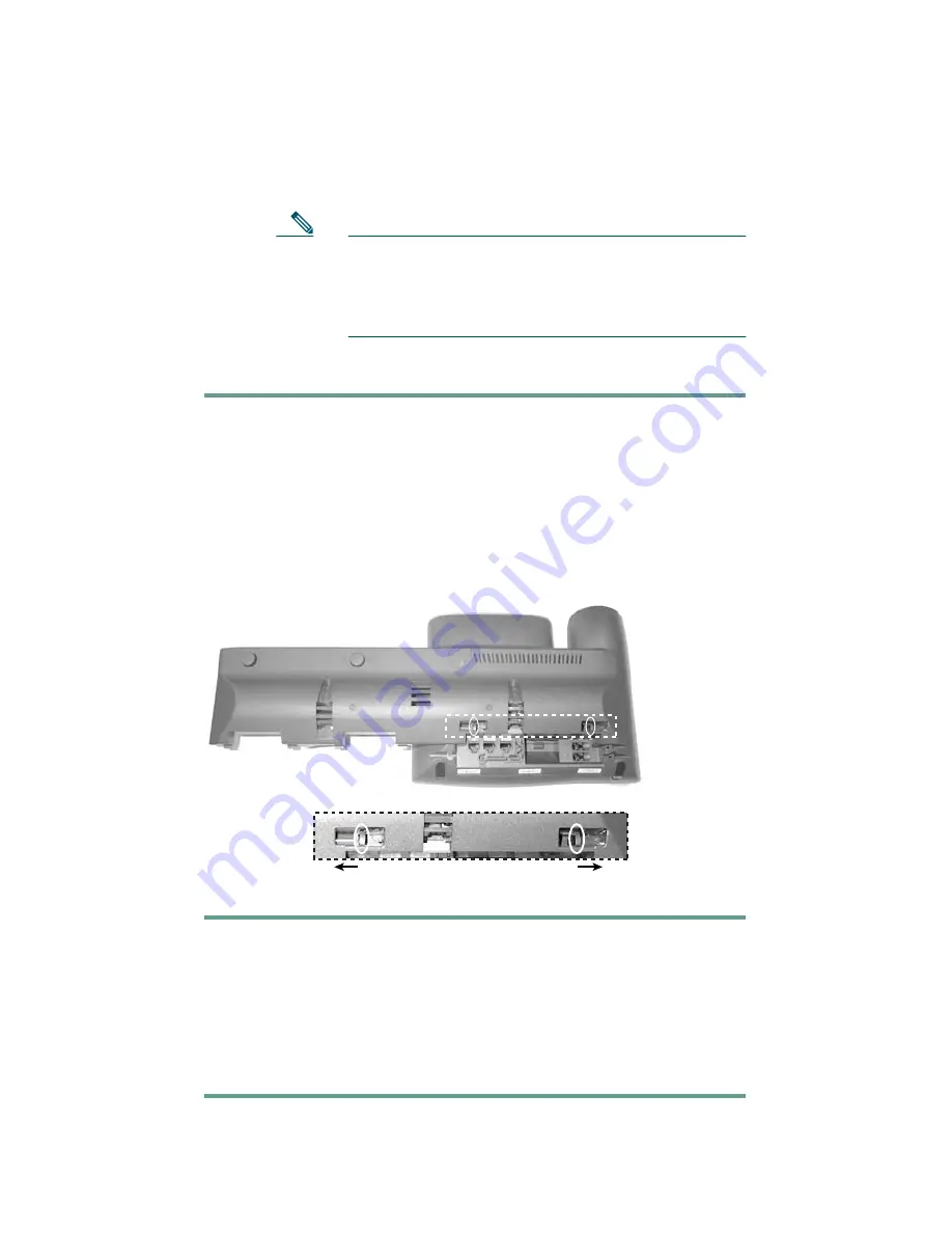
Figure 3

Connecting the Support Bar

Step 1

Position the support bar on the back of the 
Cisco IP Phone so that it fits flush with the phone. 

Step 2

Locate the two connector pins.

Step 3

Use a flat head screwdriver to carefully push each of the 
connector pins so that the support bar is firmly fastened 
to the Cisco IP Phone.

140969

140969

Содержание Expansion Module 7914

Страница 1: ...the Expansion Module 7914 3 Features of the Expansion Module 7914 4 Using the Expansion Module 7914 5 Troubleshooting the Expansion Module 7914 6 Technical Specifications for the Expansion Module 7914 7 Where to Find More Information 8 Cisco Product Security Overview 9 Obtaining Technical Assistance 10 Cisco One Year Limited Hardware Warranty Terms ...

Страница 2: ...total of 28 extra line appearances or programmable buttons to your phone The programmable buttons can be configured for speed dial numbers or to access phone services Note For the latest information about supported phone models contact your system administrator Figure 1 Cisco IP Phone 7960G with 2 Expansion Modules Before You Begin Before you begin installing your Expansion Module 7914 read each o...

Страница 3: ...otstand Kit If you are attaching two Expansion Module 7914s you need the double Footstand Kit The Footstand Kit contains One support bar single with one thumbscrew or double with two thumbscrews One footstand Additional Equipment You also need the following equipment Small flat head screwdriver for use during the installation Power supply unit depending on how many Expansion Modules you are instal...

Страница 4: ...injury Before you work on any equipment be aware of the hazards involved with electrical circuitry and be familiar with standard practices for preventing accidents Use the statement number provided at the end of each warning to locate its translation in the translated safety warnings that accompanied this device SAVE THESE INSTRUCTIONS Warning Read the installation instructions before you connect ...

Страница 5: ...ts use RJ 45 connectors Use caution when connecting cables Using an External Power Supply The following warnings apply when you use the external power supply with the Expansion Module 7914 Warning This product relies on the building s installation for short circuit over current protection Ensure that a fuse or circuit breaker no larger than 120 VAC 15A U S 240 VAC 10A international is used on the ...

Страница 6: ...rt Bar to the Cisco IP Phone 3 Connect the Expansion Module 7914 to the Support Bar 4 Connect the Interface Cable 5 Connect the Power Supply 6 Connect the Footstand 7 Connect a Laptop Cable Lock optional Refer to the detailed instructions and corresponding illustrations that follow for each of these high level steps Caution To ensure a successful installation verify with your system administrator ...

Страница 7: ...otstand Step 1 Unplug the Cisco IP Phone network and power connections Step 2 Unplug the handset and unplug the headset if one is attached to the phone Step 3 Turn the Cisco IP Phone over and lay it on a protected flat surface to prevent it from being scratched Step 4 Locate the two foot pins on the footstand 63147 ...

Страница 8: ... your body Step 6 Lift off the footstand and store it separately Connect the Support Bar to the Cisco IP Phone Refer to Figure 3 and the steps that follow Figure 3 Connecting the Support Bar Step 1 Position the support bar on the back of the Cisco IP Phone so that it fits flush with the phone Step 2 Locate the two connector pins Step 3 Use a flat head screwdriver to carefully push each of the conn...

Страница 9: ...the Expansion Module 7914 to the Support Bar Refer to Figure 4 and the steps that follow Figure 4 Connecting the Expansion Module 1 Open slots on the Expansion Module 7914 2 Hooks on the support bar 3 Thumbscrews ...

Страница 10: ...th the bar Step 4 Tighten the thumbscrew on the back of the Expansion Module 7914 Note If you are installing two Expansion Modules repeat Steps 2 3 and 4 for the second Expansion Module Connect the Interface Cable Refer to the following table which depicts the in and out icons on the AUX jacks and to Figure 5 and the steps that follow Note On your Cisco IP Phone or Expansion Module 7914 the AUX ja...

Страница 11: ... Expansion Module 7914 continue with Steps 3 and 4 Otherwise go to the Connect the Power Supply section on page 12 1 Interface cable connection to the AUX jack on the Cisco IP Phone 2 Interface cable connection to the AUX jack labeled with the in icon on Expansion Module 1 3 Second interface cable connection to the AUX jack labeled with the out icon on Expansion Module 1 4 Second interface cable c...

Страница 12: ...he phone Step 4 Plug the other end of the second interface cable into the AUX jack with the in icon underneath on the second Expansion Module the one next to the first Expansion Module Connect the Power Supply Refer to Figure 6 and the steps that follow Figure 6 Connecting the Power Supply 1 Power supply connector on the back of the Expansion Module ...

Страница 13: ... Expansion Module closest to the Cisco IP Phone and plug the other end into a standard electrical power outlet in the wall If your Cisco IP Phone is powered with a power supply unit with one Expansion Module reconnect the original Cisco IP Phone power supply unit to the AC adapter port on the Cisco IP Phone and plug the other end into a standard electrical power outlet in the wall If your Cisco IP...

Страница 14: ... the hooks so that they align with the open slots on the support bar Note There are four positions in each of the three sets of open slots on the support bar This lets you choose the angle of the footstand Step 3 Insert the footstand hooks into the support bar and push in slightly to make the connection 1 Slots on the support bar 2 Hooks on the footstand 2 140968 1 ...

Страница 15: ...dministrator for more information Refer to Figure 8 and the steps that follow Figure 8 Connecting a Laptop Cable Lock Step 1 Detach the cable lock door from the support bar Step 2 Secure the security cable to a desktop Step 3 Insert the laptop cable lock into the security slot on the back of the phone lock it and remove the key 140967 140967 ...

Страница 16: ... the LCD screen You can then start using the Expansion Module 3 Features of the Expansion Module 7914 The Expansion Module 7914 includes the following features 1 Phone screen Displays the phone number speed dial number or name or other text label phone service or Privacy assigned to each button Icons indicating line status appear similar to and function the same as those on the Cisco IP Phone to w...

Страница 17: ...our Expansion Module 7914 and see that your Director has a call in progress with another party and also has another call on hold Looking down the Expansion Module 7914 screen you note that another manager in your group has just completed a call and could possibly assist the incoming caller You consult briefly with the incoming caller and then transfer the call to the manager 2 Lighted Buttons 14 b...

Страница 18: ...Similar to your Cisco IP Phone you can configure speed dial numbers or program buttons to access phone services on the Expansion Module 7914 Before you can do this ask your system administrator for the following information to access your Cisco IP Phone User Options web page the URL your user name and password After you have this information you can configure your speed dial numbers or program but...

Страница 19: ...co IP Phone Expansion Module 7914 as well as the regulatory compliance information Problem Solution No display on the Expansion Module 7914 Verify that all of the cable connections are correct Verify that you have power to the Expansion Module 7914 s Buttons on the first Expansion Module 7914 are all red Verify with your system administrator that your Expansion Module 7914 is defined in Cisco Call...

Страница 20: ...12A is 0 1 in 2 5 mm The center pin is positive voltage The miniature power plug required to mate with the power jack on the Expansion Module is a Switchcraft 760 or equivalent Specification Value or Range Operating Temperature 32 to 104 F 0 to 40 C Operating relative humidity 10 to 95 noncondensing Storage temperature 14 to 140 F 10 to 60 C Height 203 mm 8 0 in Width 121 mm 4 75 in Depth 51 mm 2 ...

Страница 21: ...uctions for using the Cisco IP Phone http www cisco com univercd cc td doc product voice c_ipphon index htm Cisco CallManager documentation Provides instructions for using the Cisco CallManager Administration application to configure Cisco IP Phones and services http www cisco com univercd cc td doc product voice c_callmg index htm Obtaining Documentation Cisco documentation and additional literat...

Страница 22: ...n HTML With the DVD you have access to the same documentation that is found on the Cisco website without being connected to the Internet Certain products also have pdf versions of the documentation available The Product Documentation DVD is available as a single unit or as a subscription Registered Cisco com users Cisco direct customers can order a Product Documentation DVD product number DOC DOCD...

Страница 23: ...tems Attn Customer Document Ordering 170 West Tasman Drive San Jose CA 95134 9883 We appreciate your comments Obtaining Additional Publications and Information Information about Cisco products technologies and network solutions is available from various online and printed sources Cisco Marketplace provides a variety of Cisco books reference guides documentation and logo merchandise Visit Cisco Mar...

Страница 24: ...streamline their business and expand services The publication identifies the challenges facing these companies and the technologies to help solve them using real world case studies and business strategies to help readers make sound technology investment decisions You can access iQ Magazine at this URL http www cisco com go iqmagazine or view the digital edition at this URL http ciscoiq texterity c...

Страница 25: ...ecurity Vulnerability Policy portal at this URL http www cisco com en US products products_security_vulne rability_policy html From this site you can perform these tasks Report security vulnerabilities in Cisco products Obtain assistance with security incidents that involve Cisco products Register to receive security information from Cisco A current list of security advisories and notices for Cisc...

Страница 26: ...302 1 408 525 6532 Tip We encourage you to use Pretty Good Privacy PGP or a compatible product to encrypt any sensitive information that you send to Cisco PSIRT can work from encrypted information that is compatible with PGP versions 2 x through 8 x Never use a revoked or an expired encryption key The correct public key to use in your correspondence with PSIRT is the one linked in the Contact Summ...

Страница 27: ... you can register at this URL http tools cisco com RPF register register do Note Use the Cisco Product Identification CPI tool to locate your product serial number before submitting a web or phone request for service You can access the CPI tool from the Cisco Technical Support Documentation website by clicking the Tools Resources link under Documentation Tools Choose Cisco Product Identification T...

Страница 28: ... assigned immediately to S1 and S2 service requests to help keep your business operations running smoothly To open a service request by telephone use one of the following numbers Asia Pacific 61 2 8446 7411 Australia 1 800 805 227 EMEA 32 2 704 55 55 USA 1 800 553 2447 For a complete list of Cisco TAC contacts go to this URL http www cisco com techsupport contacts Definitions of Service Request Se...

Страница 29: ...rranties and license agreements applicable to Cisco software is available on Cisco com Follow these steps to access and download the Cisco Information Packet and your warranty and license agreements from Cisco com 1 Launch your browser and go to this URL http www cisco com univercd cc td doc es_inpck cetrans htm The Warranties and License Agreements page appears 2 To read the Cisco Information Pac...

Страница 30: ...ine or click the PDF icon to download and print the document in Adobe Portable Document Format PDF You can also contact the Cisco service and support website for assistance http www cisco com public Support_root shtml Duration of Hardware Warranty One 1 Year Replacement Repair or Refund Policy for Hardware Cisco or its service center will use commercially reasonable efforts to ship a replacement p...

Страница 31: ...sed the product If you purchased the product directly from Cisco contact your Cisco Sales and Service Representative Complete the information below and keep it for reference Company product purchased from Company telephone number Product model number Product serial number Maintenance contract number ...

Страница 32: ...rica Spain Sweden Switzerland Taiwan Thailand Turkey Ukraine United Kingdom United States Venezuela Vietnam Zimbabwe 2005 Cisco Systems Inc All rights reserved Printed in Malaysia 78 13014 07 CCSP CCVP the Cisco Square Bridge logo Follow Me Browsing and StackWise are trademarks of Cisco Systems Inc Changing the Way We Work Live Play and Learn and iQuick Study are service marks of Cisco Systems Inc...

Отзывы: