background image

The illustrations in this document show all available connections for the access point. Unused connections
are capped with a connector plug to ensure the dust/watertight integrity of the access point. See the "Working
with the Access Cover" section for further details.

Note

Internal Connectors

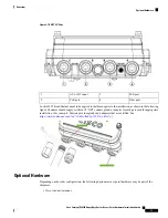
The following figure shows the IW-6300H Access Point Internal Connectors.

Figure 2: IW-6300H Access Point Internal Connectors

USB port

5

Power-IN (IW-6300H-DC-X-K9)

1

SFP port

6

PoE In port

2

Terminal block location of
IW-6300H-AC-X-K9 and
IW-6300H-DCW-X-K9

7

PoE Out port

3

Internal ground

4

Console Port and Reset Button

The console port and reset button are under a covering M25 plug located on the side of the access point, as
shown in the following figure.

Cisco Catalyst IW6300 Heavy Duty Series Access Point Hardware Installation Guide

5

Overview

Internal Connectors

Содержание Catalyst IW6300 Series

Страница 1: ...s Point Hardware Installation Guide First Published 2019 12 13 Last Modified 2020 01 15 Americas Headquarters Cisco Systems Inc 170 West Tasman Drive San Jose CA 95134 1706 USA http www cisco com Tel 408 526 4000 800 553 NETS 6387 Fax 408 527 0883 ...

Страница 2: ...s 9 Power Injectors 9 Ethernet PoE Ports 9 Fiber Option 10 I O Ports 10 Optional Hardware 11 Finding the Product Serial Number 12 Related Documentation 12 Before You Begin 13 C H A P T E R 2 Unpacking the Access Point 13 Package Contents 13 Tools and Hardware 14 Optional Tools and Hardware 14 Optional Tools and Hardware That You Supply 14 Cisco Catalyst IW6300 Heavy Duty Series Access Point Hardwa...

Страница 3: ... the Access Point on a Pole 26 Assembling the Pole Clamp Bracket and the Mounting Bracket 26 Pole Mounting 28 Working with the Access Cover 33 Opening the Access Cover 33 Closing the Access Cover 34 Installing External Antennas 35 Antenna Selection Examples 36 Non Cisco Antennas 38 Grounding the Access Point 38 Using the Reset Button 39 Powering the Access Point 40 Connecting a Power Injector 41 C...

Страница 4: ...D I X A Manufacturer Federal Communication Commission Declaration of Conformity Statement 57 Requirements Of Operator To Register The RLAN Device Operating Outdoors In The 5150 5250 MHz Band And Addressing Possible Interference Issues In This Band 58 Industry Canada 59 Canadian Compliance Statement 59 Declaration of Conformity for RF Exposure 60 European Community Switzerland Norway Iceland and Li...

Страница 5: ...nslation 66 English Translation 66 Statement 371 Power Cable and AC Adapter 67 English Translation 67 EU Declaration of Conformity 67 Access Point Specifications 69 A P P E N D I X B Technical Specifications 69 Power Consumption Budget 71 Access Point Pinouts 73 A P P E N D I X C Access Point Pinouts 73 Cisco Catalyst IW6300 Heavy Duty Series Access Point Hardware Installation Guide v Contents ...

Страница 6: ...Cisco Catalyst IW6300 Heavy Duty Series Access Point Hardware Installation Guide vi Contents ...

Страница 7: ... Increase the separation between the equipment and receiver Connect the equipment into an outlet on a circuit different from that to which the receiver is connected Consult the dealer or an experienced radio TV technician for help Modifications to this product not authorized by Cisco could void the FCC approval and negate your authority to operate the product The Cisco implementation of TCP header...

Страница 8: ......

Страница 9: ...erms and concepts For installations in a hazardous locations environment please refer to Getting Started and Product Document of Compliance for the Cisco Catalyst IW6300 Heavy Duty Series Access Points for additional installation information Only trained and qualified personnel should be allowed to install replace or service this equipment Statement 1030 Warning Conventions This publication uses t...

Страница 10: ...accidents Use the statement number provided at the end of each warning to locate its translation in the translated safety warnings that accompanied this device Statement 1071 SAVE THESE INSTRUCTIONS Warning About the Access Point Designed for the most hazardous industrial locations Cisco Catalyst IW6300 Heavy Duty Access Points deliver wireless connectivity IoT control and robust data collection t...

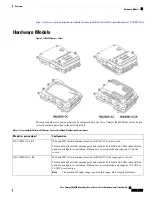
Страница 11: ...fied AC power version This model has 4 external antenna ports and contains a 2 4 GHz and 5 GHz radio with an option to configure in centralized Flexconnect or mesh mode and supports AC power source IW 6300H AC x K9 IP66 and IP67 rated hazardous location certified DC wide range power version This model has 4 external antenna ports and contains a 2 4 GHz and 5 GHz radio with an option to configure i...

Страница 12: ...thernet Ports Antenna Ports Power Option Product PID Four 1 2 NPT Ports 35 3W One 100 1000Mbps SFP for WAN One 100 1000Mbps RJ45 for WAN UPoE or PoE in Two 100 1000Mbps RJ45 for LAN 802 3at or 802 3af out Four Type N Connectors UPoE PoE AC 100V to 240V IW 6300H AC x K9 UPoE PoE DC 10 8V to 36V IW 6300H DCW x K9 UPoE PoE DC 44V to 57V IW 6300H DC x K9 For DC SKU if you want to output 802 3at type 2...

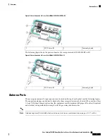
Страница 13: ...H Access Point Internal Connectors Figure 2 IW 6300H Access Point Internal Connectors USB port 5 Power IN IW 6300H DC X K9 1 SFP port 6 PoE In port 2 Terminal block location of IW 6300H AC X K9 and IW 6300H DCW X K9 7 PoE Out port 3 Internal ground 4 Console Port and Reset Button The console port and reset button are under a covering M25 plug located on the side of the access point as shown in the...
Страница 14: ...lug properly it will not meet IP66 67 criteria and may lead to water leaking into the unit Power Connector The following figure shows the power connector of access point model IW 6300H AC x K9 Figure 4 Power Connector of Access Point Model IW 6300H AC x K9 Internal ground 2 AC Power IN 1 The following figure shows the power connector of access point model IW 6300H DCW x K9 Cisco Catalyst IW6300 He...

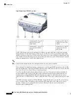
Страница 15: ... on the top of each model see the following figure The supported antennas can be directly attached to the access point or remotely located When used in a Class 1 Zone 2 Division 2 hazardous location this equipment must be mounted with proper RF cables if required and electrical wiring methods that comply with the governing electrical codes Antenna caps must be installed when an antenna is not in u...

Страница 16: ... antennas antenna ports A and B support MIMO operation on the 2 4 GHz radio and antenna ports C and D support MIMO operation on the 5 GHz radio See the Cisco Catalyst IW6300 Heavy Duty Series Access Point Software Configuration Guide Use of four omnidirectional antennas attached directly to the Type N connectors is not recommended To provide omnidirectional coverage with both 2 4 and 5 GHz radios ...

Страница 17: ...complies with the safety extra low voltage SELV requirements in IEC 60950 based safety standards Statement 1033 Warning Power Injectors The IW6300 series access points support the following power injectors AIR PWRINJ 60RGD1 AIR PWRINJ 60RGD2 Power injector AIR PWRINJ 60RGDx is not certified for installation within hazardous locations environments Caution For more information about installing the A...

Страница 18: ...ugged SFP GLC LX SM RGD 1000BASE SX multi mode rugged SFP GLC SX MM RGD 100BaseBX10 U rugged SFP GLC FE 100BX URGD 100BASE FX rugged SFP GLC FE 100FX RGD 100BASE LX10 rugged SFP GLC FE 100LX RGD 1000BASE T rugged SFP GLC T RGD SFP modules are not hot swappable Plug and unplug the SFP module the AP will reboot Note Client data is passed to the network controller through the fiber connection via a f...

Страница 19: ...and or adapter for each port used for appropriate installation For example Sealcon provides glands and adapters that are certified See https www sealconex com ex 9wkuir fln65y 13897wy drrs7y Optional Hardware Depending on the order configuration the following optional access point hardware may be part of the shipment Cisco Aironet Antennas Cisco Catalyst IW6300 Heavy Duty Series Access Point Hardw...

Страница 20: ...www cisco com c en us support wireless wireless lan controller software products installation and configuration guides list html Release Notes for Cisco Wireless LAN Controllers and Lightweight Access Points http www cisco com c en us support wireless wireless lan controller software products release notes list html Cisco Mobility Express Configuration and User Guide http www cisco com c en us sup...

Страница 21: ...protects the antenna connectors during installation To unpack the access point follow these steps Procedure Step 1 Open the shipping container and carefully remove the contents Step 2 Return all packing materials to the shipping container and save it Step 3 Ensure that all items listed in Package Contents on page 13 are included in the shipment If any item is damaged or missing notify your sales r...

Страница 22: ...wrench handle to remove 1 2 NPT port plugs Loctite 565 Thread Sealant for 1 2 NPT Ports 6 AWG copper ground wire Ethernet RJ 45 connector and installation tool Optional ground rod as required by local regulations Optional ladder power lift rope or other tools as required ESD preventive cord and wrist strap Wire stripping tools for stripping 14 and 18 gauge wires Crimping tool If installed in a haz...

Страница 23: ...l integrity of the installation by the local authority inspection department Caution This equipment must be externally grounded using a customer supplied ground wire before power is applied Contact the appropriate electrical inspection authority or an electrician if you are uncertain that suitable grounding is available Statement 366 Warning Read the installation instructions before connecting the...

Страница 24: ...for installation in restricted access areas A restricted access area can be accessed only through the use of a special tool lock and key or other means of security Statement 1017 Warning This equipment must be grounded Never defeat the ground conductor or operate the equipment in the absence of a suitably installed ground conductor Contact the appropriate electrical inspection authority or an elec...

Страница 25: ...s largely a matter of coordination Each person should be assigned to a specific task and should know what to do and when to do it One person should be in charge of the operation to issue instructions and watch for signs of trouble When installing the access point and antennas remember Do not use a metal ladder Do not work on a wet or windy day Do dress properly shoes with rubber soles and heels ru...

Страница 26: ...na port from one access point to the antenna port of another access point without using an RF attenuator If you connect antenna ports you must not exceed the maximum survivable receive level of 0 dBm Never exceed 0 dBm or damage to the access point can occur It is recommended to keep the received signal strength at or below 30 dBm to avoid degraded PER Using attenuators combiners and splitters hav...

Страница 27: ... in contact with a power line do not touch it or try to remove it yourself Call your local power company to have it removed safely 8 If an accident should occur with the power lines call for qualified emergency help immediately Installation Guidelines Because the access point is a radio device it is susceptible to common causes of interference that can reduce throughput and range Follow these basi...

Страница 28: ...environment Clear or open areas provide better radio range than closed or filled areas Obstructions Physical obstructions such as buildings trees or hills can hinder performance of wireless devices Avoid locating the devices in a location where there is an obstruction between the sending and receiving antennas Applications and type of devices to be used on the WLAN Before Beginning the Installatio...

Страница 29: ...s access points and bridging techniques and grounding methods All installation methods for mounting an access point on any wall surface is subject to the acceptance of local jurisdiction Caution Installation Option The Cisco Catalyst IW6300 Heavy Duty Series Access Points are installed using the pole mount installation kit IOT ACCPMK which is used for pole or wall installations Only trained and qu...

Страница 30: ... and the access cover facing out This positioning allows the LEDs to be visible to someone on the ground below the access point and the I O interfaces are on the bottom to minimize moisture ingress in case ports are not adequately sealed Omnidirectional antennas are vertically polarized and should be mounted vertically Note The following figures show the dimension of the access point Figure 9 Unit...

Страница 31: ...he following table lists the material that you will need to provide in addition to the pole mount kit Table 3 Material Needed to Mount Access Point to a Vertical Wall In Kit Materials Required Yes Ground lug and screws provided with access point No Crimping tool for ground lug No Four M8 or 5 16 in 31 mm screws No Four wall anchors specified for wall material No Drill bit for wall anchors Cisco Ca...

Страница 32: ...ght Caution The mounting bracket can be used as a template to mark the screw hole locations To mount the access point on a vertical wall follow these instructions Procedure Step 1 Use the mounting bracket as a template to mark four screw hole locations on your mounting surface You can optionally use the individual mounting holes or the mounting slots Figure 11 Mounting Bracket Dimension Cisco Cata...

Страница 33: ...cco cement or drywall Note Step 3 Screw a M8 x16 bolt in the top support bolt hole on each side the access point Do not screw the bolt all the way in leave approximately a 0 25 inch 0 635 cm space Step 4 Position the two bolts on the access point onto the hands free attach points on each side of the mounting bracket Ensure that the access point cover is facing out Never leave the access point unat...

Страница 34: ...40 Mounting the Access Point on a Pole When installing an access point on a vertical pole you should use the optional Cisco pole mount kit The kit supports metal wood or fiberglass poles from 2 to 16 inches in diameter Assembling the Pole Clamp Bracket and the Mounting Bracket The pole mount kit contains several parts that you must assemble prior to mounting on a pole First you need to assemble tw...

Страница 35: ... cm 1 To assemble the pole clamp bracket follow these steps Procedure Step 1 Position the strap brackets on the pole clamp bracket for the pole diameter you are using and secure each strap bracket with two M8 x16 bolts with lock washers Tighten the bolts to 13 to 15 ft lbs 17 6 to 20 3 Nm Cisco Catalyst IW6300 Heavy Duty Series Access Point Hardware Installation Guide 27 Installing the Access Poin...

Страница 36: ... just enough to prevent the bolt from falling off Step 3 Go to Pole Mounting on page 28 Pole Mounting To mount your access point on a vertical pole you need to install two metal bands around the pole to support the access point This process requires extra tools and material not provided in the pole mount kit see the following table Cisco Catalyst IW6300 Heavy Duty Series Access Point Hardware Inst...

Страница 37: ...You can attach the access point to any pole from 2 to 16 inch 5 1 to 40 6 cm in diameter Step 2 For poles larger than 3 5 inch 8 9 cm mount the pole clamp bracket assembly to a pole using two metal straps Following the instructions provided with the banding strap tool BAND IT AIR BAND INST TL loop each metal strap twice through the slots on the strap bracket Do not place the metal straps in the la...

Страница 38: ...e Step 5 Tighten the metal bands using the banding strap tool BAND IT Cisco AIR BAND INST TL by following the operating instructions in the box with the tool Ensure that the metal bands are as tight as possible Step 6 Place the mounting bracket onto the pole clamp bracket support bolt Step 7 Install four M8 x16 bolts with flat and lock washers into the bolt holes Step 8 Hand tighten the bolts and ...

Страница 39: ...t to Hands Free Attach Point with Top Support Bolts Hands free attach point 3 Top Support M8 x16 bolt hole 1 Second M8 x16 bolt hole 2 Step 12 Screw a M8 x16 bolt with flat and lock washers into the second bolt hole on each side of the access point Cisco Catalyst IW6300 Heavy Duty Series Access Point Hardware Installation Guide 31 Installing the Access Point Pole Mounting ...

Страница 40: ...lt 1 Step 13 Ensure that the front of the access point is vertical and tighten the four bolts to 13 to 15 ft lbs 17 6 to 20 3 Nm Cisco Catalyst IW6300 Heavy Duty Series Access Point Hardware Installation Guide 32 Installing the Access Point Pole Mounting ...

Страница 41: ... on page 38 and Powering the Access Point on page 40 Working with the Access Cover This section details opening and closing the access cover of the access point Opening the Access Cover The access cover must not be opened unless the area is considered non hazardous and the AP has been powered off Caution You need to open the access cover to access the AC or DC terminal block the Ethernet ports and...

Страница 42: ... 1 Ensure that O ring sealing surface is free of debris and that O ring is undamaged and fully contained in groove Step 2 When closing the access cover be careful not to pinch internal wires Step 3 Carefully position the cover flush with all sides of the access point then slowly hand tighten each bolt Step 4 When all bolts are hand tightened use a 13 mm closed end wrench or socket to partially tig...

Страница 43: ... AIR ANT2588P3M N Directional dual polarized 4 port 13 13 dBi 2 4 5 GHz AIR ANT2513P4M N Omnidirectional vertically polarized white 5 dBi 2 4 GHz AIR ANT2450V N Omnidirectional vertically polarized white for Hazardous Locations 5 dBi 2 4 GHz AIR ANT2450V N HZ Omnidirectional vertically polarized gray 5 dBi 2 4 GHz AIR ANT2450VG N Omnidirectional horizontally polarized gray 5 dBi 2 4 GHz AIR ANT245...

Страница 44: ...ctional access coverage on both radios Single band Connect the two 2 4 GHz omnidirectional antennas directly to ports A and B Mount the 5 GHz directional antenna with the included hardware and connect it to ports C and D via the adapters coaxial cables and lightning arrestors if required 2x N m N f Lightning Arrestor CGR LA NM NF and 2x N f N f adapter AIR ACC370 NF NF 2x N m N m cables CAB L400 5...

Страница 45: ...on 2 4 GHz Dual band Connect the coax cables from Ports A and B to the two outer ports of the antenna Terminate the unused middle port of the antenna and Ports C and D of the IW 6300 with a weatherproof cap Use lightning arrestors if required 2x N m N f Lightning Arrestor CGR LA NM NF 2x N m N m cables CAB L400 5 N N CAB L400 5 N NS CAB L400 20 N N CAB L600 30 N N or AIR CAB025HZ N 1x 2 4 GHz 5 GH...

Страница 46: ...ical Assistance Center will not be able to provide any support for third party antennas Cisco s FCC Part 15 compliance is only guaranteed with Cisco antennas or antennas that are of the same design and gain as Cisco antennas Grounding the Access Point The access point must be grounded before connecting power In all outdoor installations you must follow these instructions to properly ground the cas...

Страница 47: ...rew to 22 to 24 lb in 2 49 to 2 71 Nm Step 5 If necessary strip the other end of the ground wire and connect it to a reliable earth ground such as a grounding rod or an appropriate grounding point on a metal streetlight pole that is grounded Using the Reset Button The access point has a reset button located on the right side of the unit see the following figure Cisco Catalyst IW6300 Heavy Duty Ser...

Страница 48: ...maximum marked 100 240V 50 60Hz 1 3A IW 6300H DC x K9 44 to 57Vdc 1 2A IW 6300H DCW x K9 10 8 to 36Vdc 5 9A The marked DC input range is an absolute range Do not apply tolerances Note In all cases above the AC branch circuit powering the access point must be limited to no more than 20A from the over protection device supplied by the user This branch power protection must meet all local and nationa...

Страница 49: ...installer is responsible for ensuring that powering the access point from this type of power injector is allowed by local and or national safety and telecommunications equipment standards Note To forward bridge traffic add a switch between the power injector and controller Refer to the latest Cisco Wireless Mesh Access Points Design and Deployment Guide for more information Tip Step 3 Ensure that ...

Страница 50: ...an RJ 45 connector on the unterminated end of the Ethernet cable using your Ethernet cable installation tool To reduce the risk of fire use only No 26 AWG or larger telecommunication line cord Statement 1023 Warning Step 6 Carefully insert the RJ 45 cable connector into the Ethernet port opening on the access point and connect to the internal Ethernet connector Step 7 Ensure that the antennas are ...

Страница 51: ...t see Grounding the Access Point on page 38 Step 3 Route the AC power cable through the 1 2 NPT port Figure 24 Connecting Internal Ground and AC Power Connection for IW 6300H AC X K9 Terminal block 3 Customer supplied harness 1 Customer supplied cable ATEX only 2 Step 4 Use a wire stripper tool to remove the insulation from each wire Remove only enough wire to provide a solid connection in the ter...

Страница 52: ...ource that complies with the Safety Extra Low Voltage SELV requirements in IEC 60950 based safety standards or ES1 requirements in IEC 62368 based safety standards Statement 1033 Warning To route and connect the power cable to the IW 6300H DCW x K9 model follow these steps Procedure Step 1 Open the access point cover See Opening the Access Cover on page 33 for instructions Step 2 Ensure a 6 AWG gr...

Страница 53: ...nstallation for short circuit overcurrent protection Ensure that the protective device is rated not greater than 5 A Statement 1005 Warning A readily accessible two poled disconnect device must be incorporated in the fixed wiring Statement 1022 Warning To reduce risk of electric shock connect the unit only to DC power source that complies with the Safety Extra Low Voltage SELV requirements in IEC ...

Страница 54: ...ire Step 6 Secure DC input cord to wire tie anchor adjacent to terminal strip Step 7 Check your work Step 8 Close the access point cover See Closing the Access Cover on page 34 for details Performing Maintenance The access point requires minimal periodic or preventive maintenance as it has no moving parts filters lubricants or mechanical contact components However when installed in a hazardous loc...

Страница 55: ...ocation environment Table 6 Periodic Inspection Table on page 47 lists the inspection routines and their periodicity Table 6 Periodic Inspection Table Periodicity Inspection Routine Every 3 years Inspect O ring seals and exterior electrical connections for aging corrosion and low ground resistance Every 5 years Inspect cover and liquid tight adapter gaskets for airtightness Conducting Periodic Cle...

Страница 56: ...Cisco Catalyst IW6300 Heavy Duty Series Access Point Hardware Installation Guide 48 Installing the Access Point Conducting Periodic Cleaning ...

Страница 57: ...ts are connected to switch ports that are configured as untagged access ports A DHCP server is reachable by your access points and has been configured with Option 43 Option 43 provides the IP addresses of the management interfaces of your controllers Typically a DHCP server can be configured on a Cisco switch Optionally a DNS server can be configured to enable CISCO CAPWAP CONTROLLER Use local dom...

Страница 58: ... connections The same network must never be connected to multiple wired ports on an access point or on two bridged access points A bridge loop causes network routing problems Controller DHCP Server The controller DHCP server only assigns IP addresses to lightweight access points Ethernet bridging clients on the mesh access points and wireless clients associated to an access point It does not assig...

Страница 59: ...of installation and also every time the plug is removed and replaced Tighten the plug to 5 6 lb ft If you do not tighten the plug properly it will not meet IP67 criteria and may lead to water leaking into the unit Resetting the Access Point Using the Reset button you can Reset the AP to the default factory shipped configuration Clear the AP internal storage including all configuration files To use...

Страница 60: ...lor intensity and hue from unit to unit This is within the normal range of the LED manufacturer specifications and is not a defect Note The access point LED signals are listed in the following table Table 7 Access Point System LED Signals Meaning Color LED Message Type Boot loader status sequence DRAM memory test in progress DRAM memory test OK Board initialization in progress Initializing FLASH f...

Страница 61: ...is in progress the Reset button has been released Blinking Green There has been a DRAM memory test failure Red Boot loader errors There has been a FLASH file system failure Blinking Red and Amber This sequence may indicate any of the following Environment variable failure Bad MAC address Ethernet failure during image recovery Boot environment failure No Cisco image file Boot failure Blinking Red a...

Страница 62: ...RAPs with different BGNs and on different channels The BGN is a string of ten characters maximum A factory set bridge group name NULL VALUE is assigned during manufacturing It is not visible to you but allows new access point radios to join a network of new access points The BGN can be reconfigured from the Controller CLI and GUI After configuring the BGN the access point reboots After the access ...

Страница 63: ...Click on an access point name Step 4 Find the Mesh Information section and enter the new BGN in the Bridge Group Name field Step 5 Click Apply Step 6 Repeat Steps 2 through 5 for each access point Step 7 Log out from your controller and close your web browser Cisco Catalyst IW6300 Heavy Duty Series Access Point Hardware Installation Guide 55 Troubleshooting Changing the Bridge Group Name ...

Страница 64: ...Cisco Catalyst IW6300 Heavy Duty Series Access Point Hardware Installation Guide 56 Troubleshooting Changing the Bridge Group Name ...

Страница 65: ...nformity With Regard To The R TTE Directive 1999 5 EC on page 61 Declaration of Conformity for RF Exposure on page 63 Guidelines for Operating Cisco Catalyst Access Points in Japan on page 64 Administrative Rules for Cisco Catalyst Access Points in Taiwan on page 65 ManufacturerFederalCommunicationCommissionDeclaration of Conformity Statement FCC ID Models LDKESW6300 IW 6300H AC B K9 IW 6300H DC B...

Страница 66: ...pplied antennas Any changes or modification to the product not expressly approved by Cisco could void the user s authority to operate this device Caution To meet regulatory restrictions the access point must be professionally installed Caution Requirements Of Operator To Register The RLAN Device Operating Outdoors In The 5150 5250 MHz Band And Addressing Possible Interference Issues In This Band S...

Страница 67: ...to other users the antenna type and its gain should be so chosen that the equivalent isotropically radiated power e i r p is not more than that necessary for successful communication Conformément à la réglementation d Industrie Canada le présent émetteur radio peut fonctionner avec une antenne d un type et d un gain maximal ou inférieur approuvé pour l émetteur par Industrie Canada Dans le but de ...

Страница 68: ...ndes 5 250 5 350 MHz et 5 650 5 850 MHz et que ces radars pourraient causer du brouillage et ou des dommages aux dispositifs LAN EL Declaration of Conformity for RF Exposure This access point product has been found to be compliant to the requirements set forth in CFR 47 Section 1 1307 addressing RF Exposure from radio frequency devices as defined in Evaluating Compliance with FCC Guidelines for Hu...

Страница 69: ...d by Cisco Systems The use of software or firmware not provided and supported by Cisco Systems may result in the equipment no longer being compliant with the regulatory requirements Cisco Catalyst IW6300 Heavy Duty Series Access Point Hardware Installation Guide 61 Declarations of Conformity and Regulatory Information Declaration of Conformity With Regard To The R TTE Directive 1999 5 EC ...

Страница 70: ...MC requirements of the Medical Devices Directive 93 42 EEC This equipment is intended to be used in all EU and EFTA countries Outdoor use may be restricted to certain frequencies and or may require a license for operation For more details contact Cisco Corporate Compliance Note The product carries the CE Mark Cisco Catalyst IW6300 Heavy Duty Series Access Point Hardware Installation Guide 62 Decla...

Страница 71: ...ne est de 9 8 25 cm pour les gains d antenne jusqu à 8 dBi et 23 6 60 cm pour les gains d antenne de 14 dbi pour assurer le respect European Union This system has been evaluated for RF exposure for Humans in reference to the ICNIRP International Commission on Non Ionizing Radiation Protection limits The evaluation was based on the EN 50385 Product Standard to Demonstrate Compliance of Radio Base s...

Страница 72: ...adio stations used in factory production lines 1 Before using this equipment make sure that no premises radio stations or specified low power radio stations of RF ID are used in the vicinity 2 If this equipment causes RF interference to a premises radio station of RF ID promptly change the frequency or stop using the device contact the number below and ask for recommendations on avoiding radio int...

Страница 73: ...ative rules for operating Cisco Catalyst Access Points in Taiwan The rules are provided in both Chinese and English Chinese Translation English Translation Administrative Rules for Low power Radio Frequency Devices Article 12 For those low power radio frequency devices that have already received a type approval companies business units or users should not change its frequencies increase its power ...

Страница 74: ...c and medical ISM equipment or by an incidental radiator Chinese Translation English Translation Low power Radio frequency Devices Technical Specifications 4 7 Unlicensed National Information Infrastructure 4 7 6 The U NII devices shall accept any interference from legal communications and shall not interfere the legal communications If interference is caused the user must stop operating the devic...

Страница 75: ...r any other electrical devices than products designated by CISCO The use of cables that are certified by Electrical Appliance and Material Safety Law that have PSE shown on the code is not limited to CISCO designated products EU Declaration of Conformity All the Declaration of Conformity statements related to this product can be found at the following location http www ciscofax com Cisco Catalyst ...

Страница 76: ...Cisco Catalyst IW6300 Heavy Duty Series Access Point Hardware Installation Guide 68 Declarations of Conformity and Regulatory Information EU Declaration of Conformity ...

Страница 77: ...n x 11 in x 5 6 in 24 7 cm x 28 cm x 14 2 cm 9 7 in x 11 in x 3 8 in 24 2 cm x 28 cm x 9 65 cm 9 7 in x 11 in x 5 6 in 24 7 cm x 28 cm x 14 2 cm Size 12 7 lbs 5 76 kg 9 8 lbs 4 45 kg 13 3 lbs 6 03 kg Weight 10 8 to 36Vdc 5 9A 44 to 57VDC 1 2A 100 to 240 VAC 1 3A 50 60 Hz Power sources Four Type N antenna connectors for 2 4 GHz radio and 5 GHz 802 11ac radio depends on configuration Antenna connect...

Страница 78: ...B ICES 003 Issue 6 2016 CISPR 22 EN 55022 CISPR32 Edition 2 EN 55032 2015 EN 61000 3 2 2014 Applicable to IW 6300H AC X K9 only EN 61000 3 3 2013 Applicable to IW 6300H AC X K9 only VCCI CLASS A AS NZ CISPR32 WW EMC Emissions CLASS A CISPR24 2010 A1 2015 EN 55024 2010 A1 2015 CISPR35 EN 55035 EN 300386 V1 6 1 WW EMC Immunity Cisco Catalyst IW6300 Heavy Duty Series Access Point Hardware Installatio...

Страница 79: ...301 489 17 KN 301 489 17 Radio EMC UL CSA EN IEC 60950 1 2016 A1 2010 A11 2009 A12 2011 A2 2013 IEC 60950 1 UL CSA EN IEC 62368 1 Safety UL 50E type 4X EN IEC 60529 IP66 and IP67 UL CSA IEC 60950 22 Outdoor rating Ingress water and dust Protection Power Consumption Budget The following table lists the power consumption budget for the IW 6300H access point configurations Table 10 IW 6300H Power Con...

Страница 80: ...er Consumption 60 Total power consumption when AC powered 100 240VAC 51 7 Total power consumption when DC powered 44 57VDC 59 9 Total power consumption when DCW powered 10 8 36VDC For DC power source IW 6300H DC x K9 if you want to output 802 3at type 2 PoE out power DC input must 51V If you want to output 802 3af PoE out power DC input must 45V Note Cisco Catalyst IW6300 Heavy Duty Series Access ...

Страница 81: ...PoE Out connector Table 11 Access Point PoE Out Ethernet Connector Pinouts Signal Name Pin Number Ethernet signal pair 10 100 1000BASE T and VDC return 1 2 Ethernet signal pair 10 100 1000BASE T and VDC 3 6 Ethernet signal pair 10 100 1000BASE T 4 5 Ethernet signal pair 10 100 1000BASE T 7 8 Chassis ground Shield The following table describes the pin signals for the access point PoE In Ethernet co...

Страница 82: ...ector input connector To Switch Table 13 Power Injector AIR PWRINJ 60RGD1 and AIR PWRINJ 60RGD2 Input Connector To Switch Pinouts Signal Name Pin Number Ethernet signal pair 10 100 1000BASE T 1 2 Ethernet signal pair 10 100 1000BASE T 3 6 Ethernet signal pair 1000BASE T 4 5 Ethernet signal pair 1000BASE T 7 8 Chassis ground Shield The following table describes the RJ 45 pin signals for the power i...

Страница 83: ...BASE T and 55 VDC 3 6 Ethernet signal pair 1000BASE T and 55 VDC 4 5 Ethernet signal pair 1000BASE T and 55 VDC return 7 8 Chassis ground Shield The power injector output connector To AP only supplies 55 VDC power when the Ethernet cable is connected to the IW6300 PoE IN connector Note Cisco Catalyst IW6300 Heavy Duty Series Access Point Hardware Installation Guide 75 Access Point Pinouts Access P...

Страница 84: ...Cisco Catalyst IW6300 Heavy Duty Series Access Point Hardware Installation Guide 76 Access Point Pinouts Access Point Pinouts ...

Отзывы: