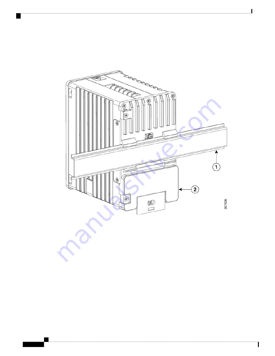
2.
Insert a tool such as a flathead screwdriver in the slot at the bottom of the spring-loaded latch and use it
to release the latch from the DIN rail.
3.
Pull the bottom of the switch away from the DIN rail, and lift the hooks off the top of the DIN rail.
Figure 7: Releasing the Spring-Loaded Latch from the DIN Rail
4.
Remove the switch from the DIN rail.
Connecting Alarm Circuits
After the switch is installed, you are ready to connect the DC power and alarm connections.
Wiring the External Alarms
The switch has two alarm input and one alarm output relay circuits for external alarms. The alarm input circuits
are designed to sense if the alarm input is open or closed relative to the alarm input reference pin. Each alarm
input can be configured as an open or closed contact. The alarm output relay circuit has a normally open and
a normally closed contact.
Alarm signals are connected to the switch through the six-pin alarm connector. Three connections are dedicated
to the two alarm input circuits: alarm input 1, alarm input 2, and a reference ground. An alarm input and the
reference ground wiring connection are required to complete a single alarm input circuit. The three remaining
connections are for the alarm output circuit: a normally open output, a normally closed output, and a common
Switch Installation
20
Switch Installation
Connecting Alarm Circuits


