32 Second-Generation Channel Interface Processor (CIP2) Installation and Configuration
Installation
Step 4
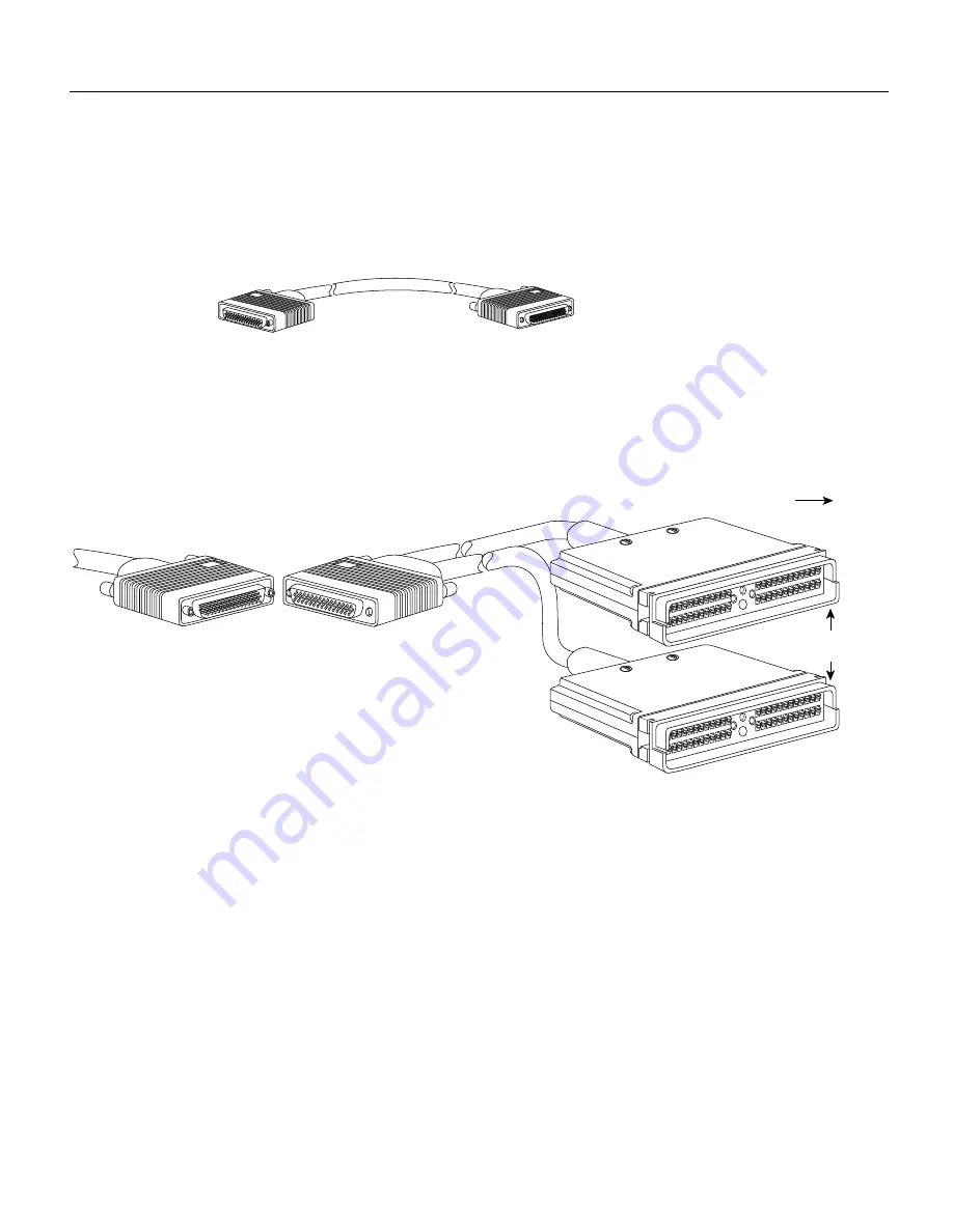
If required, extend the length of the Y cable connections (between the VA and VB cables)
with a straight-through cable (shown in Figure 19) that is available from IBM. This cable
is not available from Cisco Systems.
Figure 19
Straight-Through Cable
Step 5
Attach the male (dark gray or black) end of the Y cable to the female (light gray) end of the
VA cable that comes from the host. (See Figure 20.)
Figure 20
Connecting the VA Cable Between the Y Cable and the Host
Step 6
Leave the select/bypass switch (see Figure 6 on page 11) in bypass mode until the PCA
connector is attached to the PCA.
Step 7
Connect the Y cable to the PCA.
Step 8
Place the select/bypass switch in select mode.
Step 9
Boot up the router.
Step 10
Configure the interface on the router.
Step 11
Vary online the host channel.
For instructions on how to vary the host channel online, refer to the documentation for your
operating system.
Step 12
It is also possible to connect the PCA to the host or mainframe using the straight-through
cable (CAB-PCA-S) as shown in Figure 21.
Female
Male
78-pin
78-pin
H2455
Bus
Tag
H2451
From host
Dark gray or black
Female
Light gray
Male
Dark gray
plastic end
Y cable
VA cable


