background image

The cable management brackets for the Cisco ASR 1002-X Router contain an independent cable management
U type feature with four screws and provides cable dressing for each card module slot.

Ensure that the cable management bracket U type feature is facing upwards when you attach it to the chassis.

Note

Follow these steps to attach the cable management brackets to both sides of the Cisco ASR 1002-X Router
in the rack:

SUMMARY STEPS

1.

Align the cable management bracket to the rack mount bracket on one side of the Cisco ASR 1002-X
Router. The cable management bracket aligns to the top hole of the chassis rack mount bracket.

2.

Using a Phillips screwdriver, insert the screw through cable management bracket and into the chassis rack
mount and tighten the screw. Use the package of four screws shipped with the router.

3.

Using the bottom rack mount ear hole, insert the screw through cable management bracket and into the
chassis rack mount (see

Figure 15: Chassis Rack Mount Bracket Ear Holes for the Cable Management

Brackets, on page 25

).

DETAILED STEPS

Step 1

Align the cable management bracket to the rack mount bracket on one side of the Cisco ASR 1002-X Router. The cable
management bracket aligns to the top hole of the chassis rack mount bracket.

Step 2

Using a Phillips screwdriver, insert the screw through cable management bracket and into the chassis rack mount and
tighten the screw. Use the package of four screws shipped with the router.

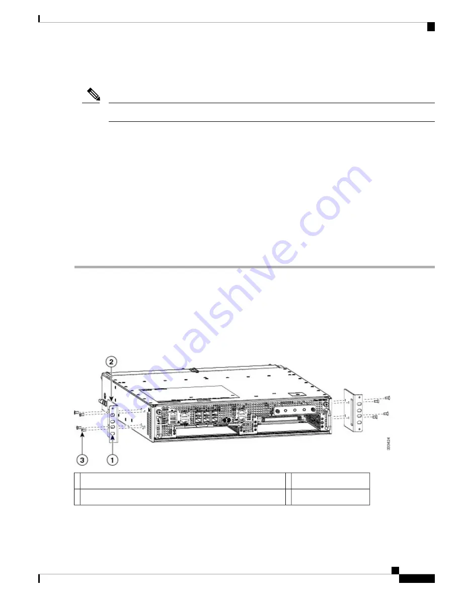
The following imave shows the locations at which to attach the front rack mount brackets to the Cisco ASR 1002-X
Router in a rack.

Figure 15: Chassis Rack Mount Bracket Ear Holes for the Cable Management Brackets

Front rack mount bracket

3

Secure the cable management top screw and bottom to this ear hole

1

Cable-management bracket

2

Cisco ASR 1002-X Router Overview and Installation

25

Cisco ASR 1002-X Router Overview and Installation

Attaching the Cable Management Bracket

Содержание ASR 1002-X

Страница 1: ...ge 29 Connecting the Console and Auxiliary Port Cables on page 29 Cisco ASR 1002 X Router Power Supplies on page 30 Connecting a Terminal to the Console Port on page 40 Connecting External Cables to the Cisco ASR 1002 X Router on page 42 Cisco ASR 1002 X Router Description The Cisco ASR 1002 X Router is a part of the Cisco ASR 1000 Aggregation Services Routers The Cisco ASR 1002 X Router is a comp...

Страница 2: ...PA SPA 2X1GE SYNCE and the Cisco WebEx Node SPA all the SPAs supported by the other Cisco ASR 1000 Series Aggregation Services Routers are supported by the Cisco ASR 1002 X Router On the Cisco ASR 1002 X Router the copper small form factor pluggable SFP port s flow control is on regardless of the duplex setting In contrast on the Cisco ASR 1002 Router the copper SFP port s flow control is off when...

Страница 3: ...SPA slot 3 3 The SPAs that you insert in slots 1 to 3 are field upgradeable Note Rear View of the Cisco ASR 1002 X Router The following image shows the Cisco ASR 1002 X Router AC power supply Figure 2 Cisco ASR 1002 X Router AC Power Supply AC power supply fan 5 Chassis ESD socket 1 Cisco ASR 1002 X Router Overview and Installation 3 Cisco ASR 1002 X Router Overview and Installation Front View of ...

Страница 4: ...le grounding lug is located on the side of the chassis Two power supplies either two AC power supplies or two DC power supplies can be accessed from the rear of the router Use only the AC power supplies or the DC power supplies in the Cisco ASR 1002 X Router Do not mix power supply types Caution Cisco ASR 1002 X Router Slot Numbering The Cisco ASR 1002 X Router contains an integrated SIP that supp...

Страница 5: ...elease Notes at http www cisco com en US docs routers asr1000 release notes asr1k_rn_rel_notes html The following table describes the LEDs on the integrated ESP Table 1 Integrated ESP LEDs Behavior in the Power Up State Color LED LED Label No All the power supplies are within operational limits Solid green Power PWR 1 Off The router is in standby mode Off The ESP is green when active Green Active ...

Страница 6: ...wo captive screws mounted on the faceplate The following table describes the AC power supply LEDs on the Cisco ASR 1002 X Router Table 2 Cisco ASR 1002 X Router AC Power Supply LEDs Description Color LED LED Label The AC input voltage is greater than 85V Green Power supply activity INPUT OK If the LED is not illuminated then either the input voltage is less than 70V or the power supply is turned o...

Страница 7: ...s turned on a threshold of 43 5 V is reached The 48 VDC power input connector accepts three wires one positive polarity one negative polarity and one ground GND wire There are provisions on the front panel to wire tie and strain relief the DC input wiring The connection order is negative positive and GND The DC power supply is secured into the system chassis with two captive screws mounted on the ...

Страница 8: ... will not create an Output Fail alarm but output voltages below the minimum limit or above the maximum limit will create an Output Fail alarm Led turns red to indicate that the DC output is out of the specified range When you turn on the power supply the LED turns red for two to three seconds to test the LED operation before going off Red Power supply activity OUTPUT FAIL The output voltage alarm ...

Страница 9: ...supply for the Cisco ASR 1002 X Router Figure 7 Cisco ASR 1002 X Router 24 VDC Power Supply Standby On switch 6 24 VDC terminal block 1 Captive fastener 7 Positive lead 2 Power supply tabs 8 Negative lead 3 27 VDC INPUT label 9 Ground GND lead 4 Power supply LEDs 5 The following table shows the definitions of the Cisco ASR 1002 X Router 24 VDC power supply LEDs Table 5 Cisco ASR 1002 X Router 24 V...

Страница 10: ...voltage reaches 19 0 V 0 5 V when this low voltage threshold is reached the power supply does not resume operation until the input voltage reaches 20 0 V 0 5 V When the turn on threshold of 20 V is reached then the 24 VDC power supply meets all specification requirements down to the low voltage threshold of 19 V tolerance 24 VDC Power System Output for the Cisco ASR 1002 X Router The 24 VDC power ...

Страница 11: ... MTBF does not apply above 55 C with less than two fans However all the component stress remains within the manufacturer s specified rating Thermal shutdown The 24 VDC power supply shuts down to protect its components due to excessive internal temperature The 24 VDC power supply then automatically restarts after the internal temperature returns to a safe operating level Power Cords Supported by th...

Страница 12: ...uation that could cause bodily injury Before you work on any equipment be aware of the hazards involved with electrical circuitry and be familiar with standard practices for preventing accidents Use the statement number provided at the end of each warning to locate its translation in the translated safety warnings that accompanied this device Statement 1071 Warning Before you install operate or se...

Страница 13: ...ter in an enclosed room that is not properly ventilated or air conditioned Caution Always install the heavier equipment in the lower half of a rack to maintain a low center of gravity to prevent the rack from falling over Install and use the cable management brackets included with the Cisco ASR 1002 X Router to keep the cables organized and out of the way of the cards and processors Ensure that ca...

Страница 14: ...e cable management bracket is available if you plan to install it on the front of the chassis An adequate chassis ground earth connection exists for your router chassis See the Attaching a Chassis Ground Connection on page 26 When handling the chassis always follow proper lifting practices as outlined in the Electrical Safety section on page 5 21 Equipment Shelf or Tabletop Installation Procedure ...

Страница 15: ...the threaded holes in the front sides of the chassis first holes beyond the vent holes Step 4 Align the front rack mount bracket to one side of the chassis Step 5 Insert and tighten the black screws that shipped with the chassis on one side Step 6 Repeat Step 2 through Step 3 on the other side of the chassis Use all the screws to secure the rack mount brackets to the chassis The chassis rack mount...

Страница 16: ... be mounted on either of these rack types Two post rack either 19 inch or 23 inch equipment rack Inner clearance the width between the inner sides of the two posts or rails must be at least 19 inches 48 26 cm The height of the chassis is 3 47 inches 8 8 cm Air flow through the chassis is from front to back Four post 19 inch equipment rack Inner clearance the width between the inner sides of the tw...

Страница 17: ...o ensure that the rack posts are parallel Note Step 2 Measure the space between the inner edges of the left front and right front mounting flanges on the equipment rack The space must be at least 17 7 inches 45 cm to accommodate the chassis that is 17 25 inches 43 8 cm wide and fits between the mounting posts on the rack Figure 10 Verifying the Equipment Rack Dimensions Attaching the Chassis Rack ...

Страница 18: ...ck mount bracket s top hole with the chassis first top hole behind the side vent holes 3 Insert and tighten the black screws shipped with the router on one side 4 Repeat Step 1 through Step 3 on the other side of the chassis Use the black screws to secure the rack mount brackets to the chassis 5 Install the chassis in a rack To install the Cisco ASR 1002 X Router in a rack see the information prov...

Страница 19: ...teps SUMMARY STEPS 1 Locate the threaded holes on the rear side of the chassis Ensure that you hold the rear rack mount bracket with the ear and holes facing outward and towards the rear of the chassis 2 Position the rear rack mount bracket top hole with the chassis top hole from the back 3 Insert and tighten the screws on one side 4 Repeat Step 1 through Step 3 on the other side of the chassis Us...

Страница 20: ...take special precautions to ensure that the system remains stable The following guidelines are provided to ensure your safety This unit should be mounted at the bottom of the rack if it is the only unit in the rack When mounting this unit in a partially filled rack load the rack from the bottom to the top with the heaviest component at the bottom of the rack If the rack is provided with stabilizin...

Страница 21: ...e rack To allow space to attach the cable management brackets to the chassis in the rack easily ensure that you use the rack mount bracket ear holes mentioned in the subsequent steps Tip Step 7 Hold the chassis in position against the mounting rails in the equipment rack and perform these steps a Insert the bottom screw into the second hole from the bottom of the rack mount ear and use a hand held...

Страница 22: ...he rack on both sides DETAILED STEPS Step 1 Position the chassis such that the front is closest to you and lift it carefully into the rack To prevent injury avoid any sudden twists or moves Caution The following image shows where to attach the rack mount brackets to the Cisco ASR 1002 X Router Figure 13 Attaching the Rack Mount Brackets to the Cisco ASR 1002 X Router Rack mount bracket ear and hol...

Страница 23: ...vel of the shelf Let the bottom of the chassis rest on the brackets but continue to support the chassis Lift the chassis into the rack using the side handles and grasping underneath the power supply bays with the help of another person 2 Position the chassis until the rack mounting flanges are flush against the mounting rails on the rack 3 Hold the chassis in position against the mounting rails wh...

Страница 24: ...ck mount bracket ear and holes 2 Step 5 Use a level to verify that the tops of the two brackets are level or use a measuring tape to verify that both the brackets are the same distance from the top of the rack rails What to do next This completes the procedure for installing the chassis in the rack Proceed to the Attaching the Cable Management Bracket on page 24 for information about how to contin...

Страница 25: ...ert the screw through cable management bracket and into the chassis rack mount see Figure 15 Chassis Rack Mount Bracket Ear Holes for the Cable Management Brackets on page 25 DETAILED STEPS Step 1 Align the cable management bracket to the rack mount bracket on one side of the Cisco ASR 1002 X Router The cable management bracket aligns to the top hole of the chassis rack mount bracket Step 2 Using ...

Страница 26: ... operate the equipment in the absence of a suitably installed ground conductor Contact the appropriate electrical inspection authority or an electrician if you are uncertain that suitable grounding is available Statement 1024 Warning Before you connect power or turn on power to your chassis you must provide an adequate chassis ground earth connection for the chassis The chassis ground lug two and ...

Страница 27: ...o attach the grounding lug to the chassis ground connector 6 Insert the two screws through the holes in the grounding lug 7 Use the Number 2 Phillips screwdriver to carefully tighten the screws until the grounding lug is held firmly to the chassis Do not overtighten the screws 8 Connect the opposite end of the grounding wire to the appropriate grounding point at your site to ensure an adequate cha...

Страница 28: ...is ground connector on the side of your chassis Step 5 The following image shows how to attach the grounding lug to the chassis ground connector Figure 18 Attaching a Grounding Lug to the Chassis Ground Connector Ground symbol 2 Chassis ground connector 1 Step 6 Insert the two screws through the holes in the grounding lug Cisco ASR 1002 X Router Overview and Installation 28 Cisco ASR 1002 X Router...

Страница 29: ...his router uses RJ 45 ports for both the auxiliary port and the console port On the front panel of the router the integrated route processor console port and auxiliary port are labeled CON and AUX respectively To meet Class A emission requirements shielded cables must be used for the console and auxiliary port connectors Caution Before using the console interface on the router via a terminal or PC...

Страница 30: ...ERNET port Step 2 Insert the other end of the RJ 45 cable to your management device or network What to do next A connection will not be established when setting up an out of band connection or modem connection in the auxiliary port and the console port Note Cisco ASR 1002 X Router Power Supplies This section describes the Cisco ASR 1002 X Router power supplies and how to connect them Read the safe...

Страница 31: ...rtain that suitable grounding is available Statement 1024 Warning This unit has two power supply connections All connections must be removed to de energize the unit Statement 1028 Warning This product relies on the building s installation for short circuit overcurrent protection Ensure that the protective device is rated not greater than AC power supplies 20 A and DC power supplies 30 A Statement ...

Страница 32: ... 3 AC power inlet 8 AC power supply LEDs 4 Step 2 Insert the AC power cable into the power supply AC inlet Step 3 To ensure that the AC power cord does not interfere with other cables or wires dress the AC power cable in one of the following ways Leave a small service loop in the AC power cord from the inlet and then secure the power cord through the AC power supply handle as shown in Figure 20 Po...

Страница 33: ... strain relief to the input wires is provided on the power supply The connection order is negative positive and GND However this is the order from left to right in which the terminals appear on the power supply not the order in which the leads should be connected during installation The order in which the leads should be attached is GND positive and negative The recommended branch circuit breaker ...

Страница 34: ...l alarm The Led turns red to indicate that the 48 VDC output is out of the specified range When you turn the power supply on the LED turns red for 2 to 3 seconds to test the LED operation before going off Red Power supply activity OUTPUT FAIL The color coding of the 48 VDC input power supply leads depends on the color coding of the 48 VDC power source at your site Typically green or green yellow i...

Страница 35: ...disconnect from the power supply if a great deal of strain is placed on all three leads as shown in Figure 24 Cisco ASR 1002 X Router 48 VDC Power Supply Terminal Block Cable Connections on page 35 8 Connect the ground positive and negative leads to the power source 9 Turn the branch source breaker on 10 Place the 48 VDC Standby switch in the On position The power supply LEDs light when power is s...

Страница 36: ...rap the lead wires to prevent the ground from being disconnected Caution Step 8 Connect the ground positive and negative leads to the power source Step 9 Turn the branch source breaker on Step 10 Place the 48 VDC Standby switch in the On position The power supply LEDs light when power is supplied to the router What to do next You have completed the procedure for connecting a 48 VDC power supply in...

Страница 37: ...t Statement 1046 Danger To connect the 24 VDC power supply in the Cisco ASR 1002 X Router follow these steps SUMMARY STEPS 1 At the rear of the router ensure that the power Standby switch is in the Standby position 2 Ensure that the positive and negative leads are disconnected from the site power source and the source circuit breaker is turned off 3 Using a wire stripper strip the recommended amou...

Страница 38: ...ds The stripping length is common to all types of wire used Note Figure 26 Stripping Wire for the 24 VDC Terminal Block on page 38 shows the wire strip and lead Figure 26 Stripping Wire for the 24 VDC Terminal Block Lead wire stripping area 1 Remove the covering from exactly the specified length of each wire If you strip too much of the covering exposed wire protruding from the terminal block will...

Страница 39: ...hows a lead wire that is fully inserted and the screwdriver being removed while you gently tug the lead wire Figure 30 Removing a Screwdriver from the 24 VDC Power Supply Terminal Block Gently tug the lead wire 1 Step 8 Repeat Steps 5 through Step 10 for each lead wire Figure 31 Cisco 24 VDC Power Supply Terminal Block with Lead Wires Installed on page 39 shows all the lead wires installed Figure ...

Страница 40: ...sole Port The integrated route processor has an asynchronous serial EIA TIA 232 RJ 45 console port labeled CON on its front panel You can connect this port to most types of video terminals using the console cable kit that is included with your Cisco ASR 1002 X Router The console cable kit contains One RJ 45 to RJ 45 crossover cable One RJ 45 to DB 9 female adapter A crossover cable reverses pin co...

Страница 41: ...S Step 1 Connect one end of the RJ 45 cable to the serial RJ 45 port CON on the front panel see the following image Figure 33 Cisco ASR 1002 X Router Console Port Connection on the Route Processor AUX port connection 2 CON port connection 1 Step 2 Run the cable up and through the cable management bracket and connect the other end of the RJ 45 cable to the RJ 45 adapter see Figure 33 Cisco ASR 1002...

Страница 42: ...ing guidelines in mind when connecting external cables to the Cisco ASR 1002 X Router To reduce the chance of interference avoid crossing high power lines with any interface cables Verify all the cabling limitations particularly distance before powering on the system Cisco ASR 1002 X Router Overview and Installation 42 Cisco ASR 1002 X Router Overview and Installation Connecting External Cables to...

Отзывы: