background image

23


Manufacturer:

Cisco Systems, Inc.
170 West Tasman Drive
San Jose, CA 95134-1706
USA

This device complies with Part 15 rules. Operation is subject to the following two conditions:

1.

This device may not cause harmful interference, and

2.

This device must accept any interference received, including interference that may cause undesired 
operation.

This device operates in the 5150-5250MHz and 5470-5725MHz bands and is therefore restricted to 
indoor operation only per FCC guidance. 

This equipment has been tested and found to comply with the limits of a Class B digital device, 
pursuant to Part 15 of the FCC Rules. These limits are designed to provide reasonable protection 
against harmful interference when the equipment is operated in a residential environment. This 
equipment generates, uses, and radiates radio frequency energy, and if not installed and used in 
accordance with the instructions, may cause harmful interference. However, there is no guarantee that 
interference will not occur. If this equipment does cause interference to radio or television reception, 
which can be determined by turning the equipment off and on, the user is encouraged to correct the 
interference by one of the following measures:

Reorient or relocate the receiving antenna.

Increase separation between the equipment and receiver.

Connect the equipment to an outlet on a circuit different from which the receiver is connected.

Consult the dealer or an experienced radio/TV technician.

Access Point Models

Certification Number

AIR-CAP3602E-A-K9
AIR-CAP3602I-A-K9

LDK102075

Module Models

Certification Number

AIR-RM3000AC-A-K9

LDK102086

Содержание Aironet 3600 Series

Страница 1: ...Access Point Ports and Connectors 7 Configuring the Access Point 8 Mounting the Access Point 9 Deploying the Access Point on the Wireless Network 10 Installing Modules 11 Troubleshooting 12 Declarations of Conformity and Regulatory Information 13 Configuring DHCP Option 43 and DHCP Option 60 14 Access Point Specifications 15 Obtaining Documentation and Submitting a Service Request ...

Страница 2: ... operability with leading 802 11n clients and support a mixed deployment with other access points and controllers The 3600 series access point is a controller based Unified product and supports Simultaneous dual band 2 4 GHz 5 GHz radios Integrated antennas on the 3602I access point model AIR CAP3602I x K9 External antennas for rugged 3602E access point model AIR CAP3602E x K9 Note The x in the mo...

Страница 3: ...d in the translated safety warnings document that is shipped with your access point The translated warnings are also in the Translated Safety Warnings for Cisco Aironet Access Points which is available on Cisco com Warning IMPORTANT SAFETY INSTRUCTIONS This warning symbol means danger You are in a situation that could cause bodily injury Before you work on any equipment be aware of the hazards inv...

Страница 4: ...7 9 inches 20 cm or more from the body of all persons Statement 332 Caution The fasteners you use to mount an access point on a ceiling must be capable of maintaining a minimum pullout force of 20 lbs 9 kg and must use all 4 indented holes on the mounting bracket Caution This product and all interconnected equipment must be installed indoors within the same building including the associated LAN co...

Страница 5: ...GHz 802 11n MIMO radios The 3600 series access point configurations are AIR CAP3602E x K9 two 2 4 GHz 5 GHz dual band radios up to 4 external dual band diopole antennas AIR CAP3602I x K9 two 2 4 GHz 5 GHz dual band radios with integrated dual band inverted F antennas For information on the regulatory domains shown as x in the model numbers see Regulatory Domains section on page 6 External Antennas...

Страница 6: ...ic features are as follows Dual band inverted F antenna for use in both the 2 4 GHz and 5 GHz bands Antenna unit integrated into the 3602I model access point Peak gain is approximately 2 dBi in the 2 4 GHz band and approximately 4 dBi in the 5 GHz band Regulatory Domains The 3600 series supports the following regulatory domains shown as x in the model numbers A C E I K N Q R S T Countries Supporte...

Страница 7: ...grated antennas and does not have external connectors on the top of the unit however it does have the LED indicator on top of the unit as shown in Figure 2 Figure 1 Access Point Ports and Connections top 3602E Model 1 Dual band antenna connector A 3 Dual band antenna connector C 2 Dual band antenna connector B 4 Dual band antenna connector D A D UAL BAND B D UAL BAND C D UAL BAND D D UAL BAND 1 4 ...

Страница 8: ...ED Indicator top 3602I Model The ports and connections on the bottom of the access point are shown in Figure 3 Figure 3 Access Point Ports and Connections bottom AIR3602E and 3602I Models 1 LED indicator 1 272377 2 3 4 1 5 6 6 ...

Страница 9: ... CAPWAP and LWAPP software on the controllers The functionality provided by the controller does not change except for customers who have Layer 2 deployments which CAPWAP does not support In a CAPWAP environment a wireless access point discovers a controller by using CAPWAP discovery mechanisms and then sends it a CAPWAP join request The controller sends the access point a CAPWAP join response allo...

Страница 10: ...iguration section on page 11 DHCP server discovery This feature uses DHCP option 43 to provide controller IP addresses to the access points Cisco switches support a DHCP server option that is typically used for this capability For more information about DHCP option 43 see the Configuring DHCP Option 43 and DHCP Option 60 section on page 37 DNS discovery The access point can discover controllers th...

Страница 11: ...rd the device MAC addresses from each location and return them to the person who is planning or managing your wireless network Installation Summary Installing the access point involves these operations Performing a pre installation configuration optional Mounting the access point Grounding the access point Deploying the access point on the wireless network Performing a Pre Installation Configurati...

Страница 12: ...priate Cisco wireless LAN controller guide a Make sure that access points have Layer 3 connectivity to the Cisco wireless LAN controller Management and AP Manager Interface b Configure the switch to which your access point is to attach See the Cisco Wireless LAN Controller Configuration Guide Release x x for additional information c Set the Cisco wireless LAN controller as the master so that new a...

Страница 13: ...0 multiservice platforms 3725 and 3745 multiservice access routers 3825 and 3845 integrated services routers The recommended external power supply for the access point is the Cisco AIR PWR B power supply The access point can also be powered by the following optional external power sources 1250 series access point power injector AIR PWRINJ4 Any 802 3af compliant power injector Note The 3602 series ...

Страница 14: ...n at which you intend to deploy it on the wireless network Step 5 If your access point does not indicate normal operation turn it off and repeat the pre installation configuration Note When you are installing a Layer 3 access point on a different subnet than the Cisco wireless LAN controller be sure that a DHCP server is reachable from the subnet on which you will be installing the access point an...

Страница 15: ...ff When the access point has joined a controller the LED is green if no clients are associated or blue if one or more clients are associated b If the LED is not on the access point is most likely not receiving power c If the LED blinks sequentially for more than 5 minutes the access point is unable to find its primary secondary and tertiary Cisco wireless LAN controller Check the connection betwee...

Страница 16: ...onnect to the access point s module port No special tools are required to install a module Installing a Module Follow these steps to install a module Step 1 Remove the module from the packaging Step 2 Power down the access point Step 3 Peel off the label from the back of the 3600 series access point to reveal the module port connector 1 Openings for module s antennas 2 Label covering port connecto...

Страница 17: ...o place Step 5 Screw down the thumb screws on the module Note If the screws are not tightened the module will not be recognized and may not operate correctly Make sure not to over tighten only hand tighten the screws Step 6 Power up the access point When the access point boots up it will recognize the module 345380 ...

Страница 18: ...joins it CAPWAP does not support Layer 2 The access point must get an IP address and discover the controller using Layer 3 DHCP DNS or IP subnet broadcast The access point console port is enabled for monitoring and debug purposes All configuration commands are disabled when the access point is connected to a controller Using DHCP Option 43 You can use DHCP Option 43 to provide a list of controller...

Страница 19: ...ader status sequence Blinking green DRAM memory test in progress DRAM memory test OK Board initialization in progress Initializing FLASH file system FLASH memory test OK Initializing Ethernet Ethernet OK Starting Cisco IOS Initialization successful Association status Green Normal operating condition but no wireless client associated Blue Normal operating condition at least one wireless client asso...

Страница 20: ...recovery MODE button pushed for 20 to 30 seconds Blinking green Image recovery in progress MODE button released Boot loader errors Red DRAM memory test failure Blinking red and blue FLASH file system failure Blinking red and off Environment variable failure Bad MAC address Ethernet failure during image recovery Boot environment failure No Cisco image file Boot failure Cisco IOS errors Red Software...

Страница 21: ...onfiguration payload sent from the controller to the access point You can view join related information for up to three times the maximum number of access points supported by the platform for the 2500 series controllers and the Controller Network Module within the Cisco 28 37 38xx Series Integrated Services Routers Note The maximum number of access points varies for the Cisco WiSM2 depending on wh...

Страница 22: ...errides the existing syslog server IP address the old address is erased from persistent storage and the new address is stored in its place The access point also starts sending all syslog messages to the new IP address provided the access point can reach the syslog server IP address You can configure the syslog server for access points and view the access point join information only from the contro...

Страница 23: ...the equipment is operated in a residential environment This equipment generates uses and radiates radio frequency energy and if not installed and used in accordance with the instructions may cause harmful interference However there is no guarantee that interference will not occur If this equipment does cause interference to radio or television reception which can be determined by turning the equip...

Страница 24: ...and 5 47 5 725 GHz bands this device is restricted to indoor operations to reduce any potential for harmful interference to co channel Mobile Satellite System MSS operations VCCI Statement for Japan Warning This is a Class B product based on the standard of the Voluntary Control Council for Interference from Information Technology Equipment VCCI If this is used near a radio or television receiver ...

Страница 25: ...remises radio stations and unlicensed specified low power radio stations used in factory production lines 1 Before using this equipment make sure that no premises radio stations or specified low power radio stations of RF ID are used in the vicinity 2 If this equipment causes RF interference to a premises radio station of RF ID promptly change the frequency or stop using the device contact the num...

Страница 26: ...the code for any other electrical devices than products designated by CISCO The use of cables that are certified by Electrical Appliance and Material Safety Law that have PSE shown on the code is not limited to CISCO designated products Industry Canada Canadian Compliance Statement This Class B Digital apparatus meets all the requirements of the Canadian Interference Causing Equipment Regulations ...

Страница 27: ...may require the user to obtain a license for the system according to the Canadian regulations For further information contact your local Industry Canada office This device has been designed to operate with antennas having a maximum gain of 6 dBi Antennas having a gain greater than 6 dBi are strictly prohibited for use with this device The required antenna impedance is 50 ohms To reduce potential r...

Страница 28: ...28 Declaration of Conformity with regard to the R TTE Directive 1999 5 EC Medical Directive 93 42 EEC ...

Страница 29: ...EN 301 489 1 v1 8 1 EN 301 489 17 v2 1 1 Health Safety EN60950 1 2005 EN 50385 2002 Radio EN 300 328 v 1 7 1 EN 301 893 v 1 5 1 The conformity assessment procedure referred to in Article 10 4 and Annex III of Directive 1999 5 EC has been followed ...

Страница 30: ...tute of Electrical and Electronic Engineers IEEE C 95 1 99 International Commission on Non Ionizing Radiation Protection ICNIRP 98 Ministry of Health Canada Safety Code 6 Limits on Human Exposure to Radio Frequency Fields in the range from 3kHz to 300 GHz Australia Radiation Protection Standard To ensure compliance with various national and international Electromagnetic Field EMF standards the sys...

Страница 31: ...s are based on IEEE ANSI C 95 1 92 and include a substantial safety margin designed to ensure the safety of all persons regardless of age and health As such the systems are designed to be operated as to avoid contact with the antennas by the end user It is recommended to set the system in a location where the antennas can remain at least a minimum distance as specified from the user in accordance ...

Страница 32: ... can easily do so by reorienting antennas away from the user placing the antennas at a greater separation distance than recommended or lowering the transmitter power output Additional Information on RF Exposure You can find additional information on the subject at the following links Cisco Systems Spread Spectrum Radios and RF Safety white paper at this URL http www cisco com warp public cc pd wit...

Страница 33: ...his URL www wow com com The Mobile Manufacturers Forum at this URL www mmfai org Administrative Rules for Cisco Aironet Access Points in Taiwan This section provides administrative rules for operating Cisco Aironet access points in Taiwan The rules for all access points are provided in both Chinese and English Chinese Translation ...

Страница 34: ...interference is caused to aviation safety and authorized radio station and if interference is caused the user must stop operating the device immediately and can t re operate it until the harmful interference is clear The authorized radio station means a radio communication service operating in accordance with the Communication Act The operation of the low power radio frequency devices is subject t...

Страница 35: ...ture 4 7 5 Within the 5 25 5 35 GHz band U NII devices will be restricted to indoor operations to reduce any potential for harmful interference to co channel MSS operations 4 7 6 The U NII devices shall accept any interference from legal communications and shall not interfere the legal communications If interference is caused the user must stop operating the device immediately and can t re operate...

Страница 36: ...ncia a sistemas operando em caráter primário English Translation This equipment operates on a secondary basis and consequently must accept harmful interference including interference from stations of the same kind This equipment may not cause harmful interference to systems operating on a primary basis Declaration of Conformity Statements All the Declaration of Conformity statements related to thi...

Страница 37: ...co AP c3600 Note If your access point was ordered with the Service Provider Option AIR OPT60 DHCP selected in the ordering tool the VCI string for the access point contains ServiceProvider For example a 3600 with this option will return this VCI string Cisco AP c3600 ServiceProvider The format of the TLV block is listed below Type 0xf1 decimal 241 Length Number of controller IP addresses 4 Value L...

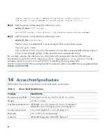
Страница 38: ...ose that there are two controllers with management interface IP addresses 10 126 126 2 and 10 127 127 2 The type is f1 hex The length is 2 4 8 08 hex The IP addresses translate to 0a7e7e02 and 0a7f7f02 Assembling the string then yields f1080a7e7e020a7f7f02 The resulting Cisco IOS command added to the DHCP scope is option 43 hex f1080a7e7e020a7f7f02 14 Access Point Specifications Table 2 lists the ...

Страница 39: ...15 109 Class B ICES 003 Class B Canada EN 301 489 EN 55022 Class B EN 55024 VCCI Class B Radio FCC Part 15 247 15 407 Canada RSS 210 Japan Telec 33 66 T71 EN 330 328 EN 301 893 FCC Bulletin OET 65C Industry Canada RSS 102 Maximum power and channel settings Maximum power and the channels allowed in your regulatory domain refer to Channels and Maximum Power Settings for Cisco Aironet Lightweight Acc...

Страница 40: ...d the Cisco logo are trademarks or registered trademarks of Cisco and or its affiliates in the U S and other countries To view a list of Cisco trademarks go to this URL www cisco com go trademarks Third party trademarks mentioned are the property of their respective owners The use of the word partner does not imply a partnership relationship between Cisco and any other company 1110R Any Internet P...

Отзывы: