


2-17
Cisco Aironet 1570 Series Outdoor Access Point Hardware Installation Guide
OL-32138-01
Chapter 2 Installing the Access Point
Installing Antennas
Step 4
Screw an M6 bolt into each of the four bolt holes on the back side of the access point. Do not screw the
bolt in all the way. Leave a gap of about 0.13" (3.3mm).
Step 5
Position the four bolts on the access point into the bracket keyhole slots. Check to be sure that the access
point is properly seated in the slots.(See
Figure 2-6
)
Note
The access point should be positioned with the LEDs on the bottom to allow viewing from the
ground.
Step 6
Using a 10mm wrench, tighten the four bolts that connect the access point to the bracket to a torque of
40 lbf-in.
Step 7
Locate the access point to its final position. Tighten the band clamps with the wrench so that the access
point does not slide on the pole. Ensure that the clamps are tight enough to not let the AP move.
Step 8
Continue with the
Grounding the Access Point, page 2-27
.
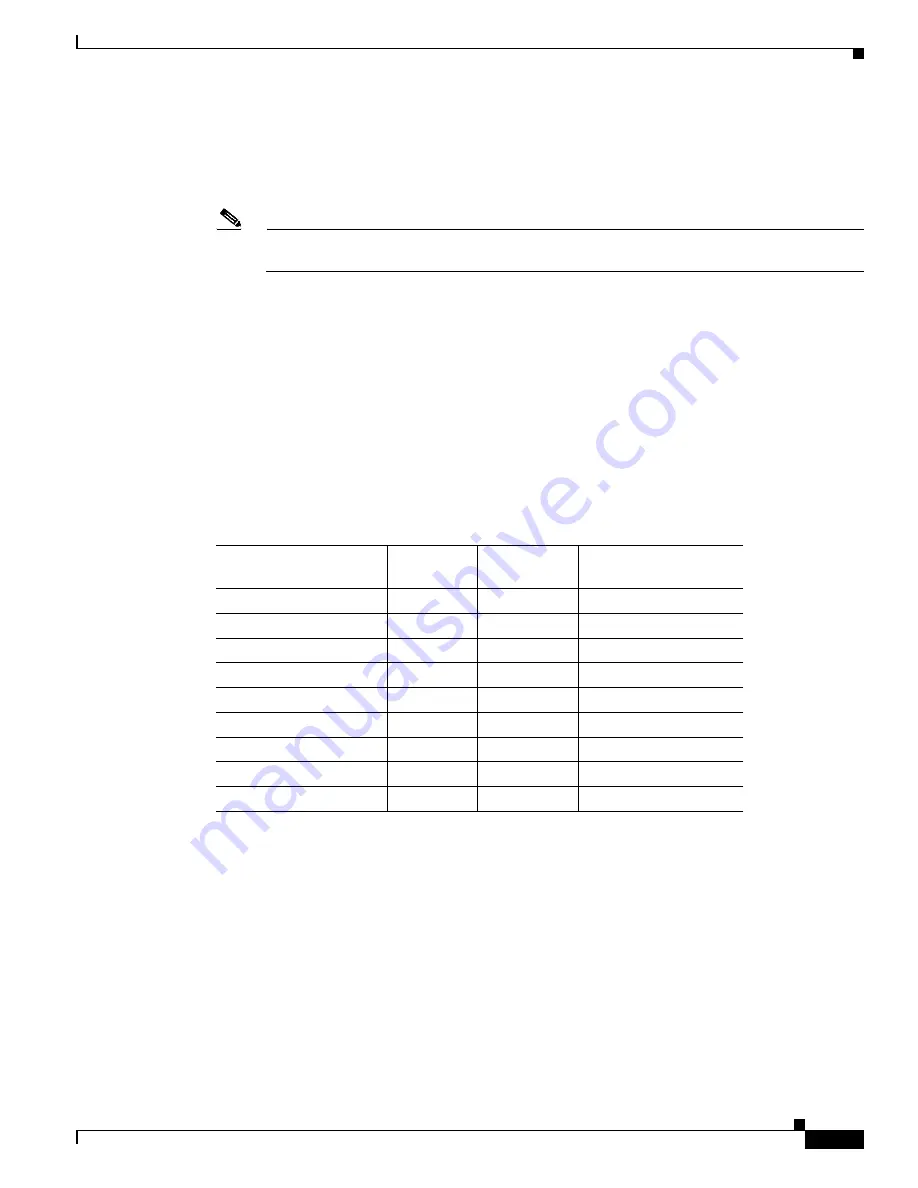
Installing Antennas
shows the antennas supported by the 1572 access point and provides required quantities for
each model.
For installation instructions and detailed information on these antennas, refer to the appropriate
document located at:
http://www.cisco.com/en/US/products/hw/wireless/ps469/prod_installation_guides_list.html
Follow all safety precautions when installing the antennas. For information on safety, refer to
Precautions when Installing Antennas” section on page 2-18
.
Table 2-3
1572 Access Point Supported External Antennas
Product ID
Frequency
Band
Gain
Type
AIR-ANT2547VG-N
2.4 / 5 GHz
4 / 7 dBi
Omnidirectional (gray)
AIR-ANT2547V-N
2.4 / 5 GHz
4 / 7 dBi
Omnidirectional (white)
AIR-ANT2588P3M-N=
2.4 / 5 GHz
4 / 7 dBi
Omnidirectional
AIR-ANT2588P3M-N
2.4 / 5 GHz
8 / 8 dBi
Directional
AIR-ANT2450V-N
2.4 GHz
5 dBi
Omnidirectional
AIR-ANT2480V-N
2.4 GHz
8 dBi
Omnidirectional
AIR-ANT2413P2M-N=
2.4 GHz
13 dBi
Directional
AIR-ANT5180V-N
5 GHz
8 dBi
Omnidirectional
AIR-ANT5114P2M-N=
5 GHz
14 dBi
Directional


