


2
Cisco 1262 Access Point Installation Manual
1. Examine the access point to see how it attaches to
the mounting bracket and to ensure that the chosen
mounting location allows clearance for the network
cable connection.
Figure 1. Low-profile Mounting Bracket Installed on an access point
2. Using the mounting bracket as a guide, mark the
position of the four mounting holes on the mounting
surface. If the network cable to the access point will
be routed through the mounting surface, cut a hole
large enough for an Ethernet cable positioned under
the cable bay area of the access point.
3. Drill the 4 mounting holes with an appropriate bit for
the metal or fiberglass vehicle surface.
4. Install stainless steel rivnuts in any holes through
fiberglass. Stainless steel self-tapping screw may
be used in any holes through metal.
5. If the network cable is routed through the mounting
surface, pull about 8 in. of cable through prior to
securing the bracket to the surface.
6. Insert machine screws in the rivnut holes and self-
tapping metal screws in any holes that are drilled
directly into metal.
Install the Power Supply
1. Position the Power Supply near the DVR.
2. Secure the power supply to the rack or mounting
surface by installing appropriate screws in the
mounting holes.
3. Connect the 48 in. power cable, UTC PN MSS-
MISC-WIFI-PS-CAB, to the Access Point Power
Supply as shown in
Error! Reference source not
ound.
below. The green terminal block snaps into
the power supply as shown. The opposite end of
the power supply cable with the Mate-N-Lok plug
connects to the vehicle wiring harness.
NOTE:
If the vehicle does not have an existing wire
harness equipped with a mating Mate-N-Lok connector
specifically to power a MobileView wireless radio at
12VDC, the connector can be removed to connect the
V+ and V- wire leads to the DVRs wiring harness (refer
to the DVR wiring pin-out diagram).
Figure 2. Connect the power cable
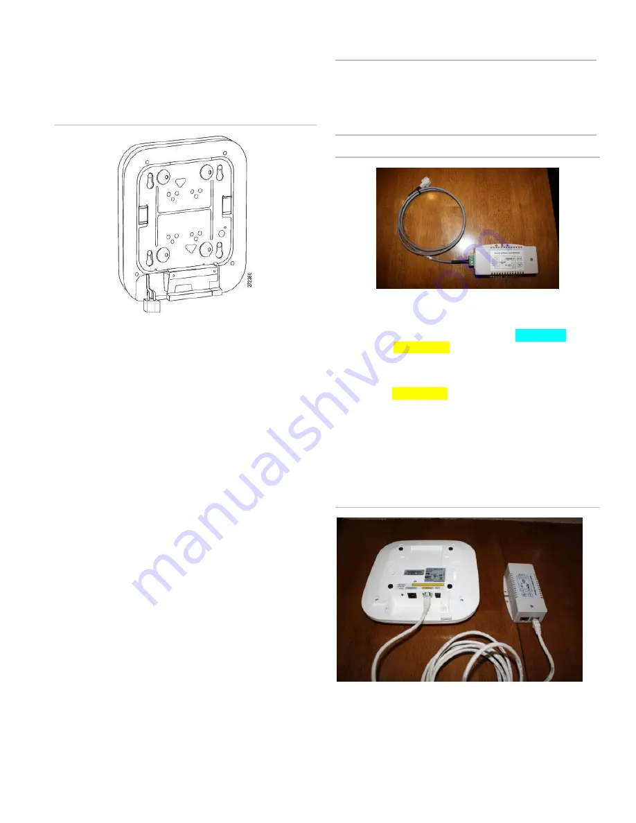
Connect the Network Cables
The access point has one port labeled CONSOLE and
one labeled ETHERNET. The power supply has one port
labeled IN and one labeled OUT.
1. Connect the network cable to the access point port
labeled ETHERNET.
2. Connect the other end of that same network cable to
the access point port labeled OUT.
3. Connect a network cable from the DVRs GIGIBIT
NET port to the IN port on the power supply.
4. Ensure that the network is wired correctly as shown
in Figure 3.
Figure 3. Network cable connection
5. Attach the access point to the mounting bracket,
tucking the cable into the cable bay area.


