


VCC-F22S29ACL
Rev.900-636-32-00
©2010 CIS Corporation. All rights reserved.
8
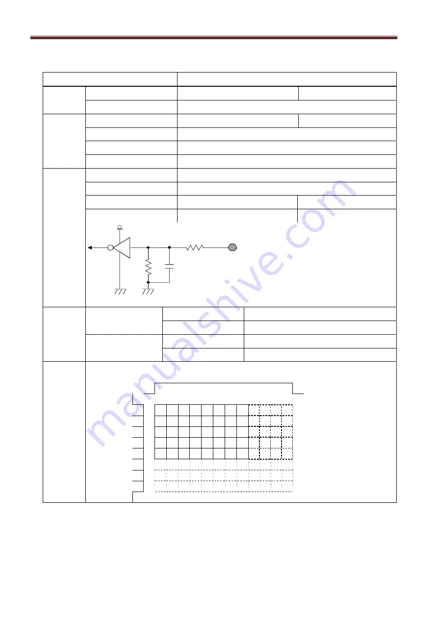
4.2. Camera Output Signal Specification
Item Specification
Video
output data
Video out
1392 (H) x 1040 (V)
At Full Frame Scan Mode
Recommended
1360 (H) x 1024 (V)
Sync.
Signal I/O
LVAL output
LVDS
Camera Link connector
FVAL output
LVDS
DVAL output
LVDS
HD/VD input
None
Trigger
input
Polarity POSI/NEGA
Selectable
Min. Trigger Pulse width Over 1 HD
Camera Link input
LVDS: CC1 input
Camera Link connector
TTL Input
Refer to the following drawing
HR10-7R-6PA
100
Ω
1 K
Ω
470p
Input
Trigger
+5V
V
IH
Min2.0V
V
IL
Max0.8V
Video
output
signal
White Clip Level
Digital 8bit
: FFh
Digital 10bit
: 3FFh
Setup Level
Digital 8bit
: 08
±
03h
Digital 10bit
: 020
±
00Ch
【
RAW Data Output Details
】
DVAL(Horizontal)
DVAL(Vertical)
R G R G R G R G
G B G B G B G B
R G R G R G R G
G B G B G B G B
R G R G R G R G
5 seconds shall be waited after turning on power to get proper camera operation.


