background image

25

Instruction Manual

RECmax Lpd

 6.- CONFIGURATION

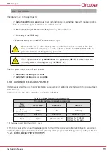
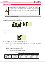
The correct operation of the 

RECmax Lpd 

depends on its correct adjustment. Since 

it is a protection device, erroneous adjustment can compromise the protection of 

property and people. That is why it is very important that it is adjusted by a trained 

technician to decide on the most appropriate type of protection in each installa-

tion.

CIRCUTOR

 accepts no responsibility for incorrect working of the device due to 

erroneous adjustment

 6�1�- EARTH LEAKAGE PROTECTION

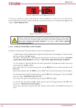
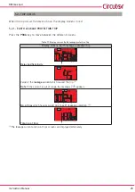
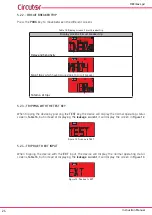
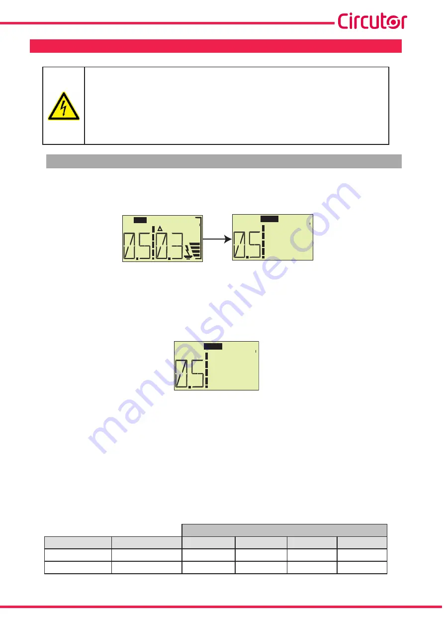
To configure the earth leakage protection, press the 

PROG

 key for more than 3 seconds, while the 

Delay and Sensitivity

 screen is displayed, 

Figure 14

.

td     s

  A

I  n

REC

td     s

PROG

PROG > 3s

Figure 14: Configuration: Earth leakage protection�

6�1�1�- ACTIVATION DELAY

Configure the activation delay value on this screen, 

Δt(td)

.

td     s

PROG

Press the 

RESET

 key to modify the value. The possible values are:


INS

, reverse curve according to the leakage current intensity measured, 

, with instantaneous 

programming. 

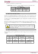
Table 19

 shows the activation times.


SEL

, reverse curve according to the leakage current intensity measured, 

, with selective pro-

gramming. 

Table 19

 shows the activation times.


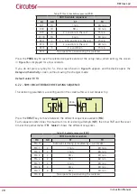
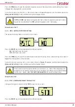
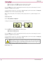
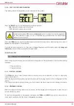
0�1s, 0�2s, 0�3s, 0�4s, 0�5s, 0�6s, 0�8s, 1s

, fixed values.

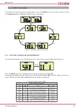
Table 19: Activation times of the reverse curve�

Maximum operating time for I

Δ


Type

I

Δ

n

I

Δ

 : 1 x I

Δ

n

I

Δ

 : 2 x I

Δ

n

I

Δ

 : 5 x I

Δ

n

500 A

INS

tantaneous

All the values

0.3 s

0.15 s

0.04 s

0.04 s

SEL

ective

> 0.03 A

0.5 s

0.2 s

0.15 s

0.15 s


Note:


Standard values of the IEC 61008-1.

Содержание RECmax Lpd

Страница 1: ...INSTRUCTION MANUAL Earth leakage circuit breaker with automatic re closing system RECmax Lpd M98252901 03 21A...

Страница 2: ...2 RECmax Lpd Instruction Manual...

Страница 3: ...a todas las instrucciones de instalaci n y mantenimiento del equipo a lo largo de la vida del mismo En particular respete las normas de insta laci n indicadas en el C digo El ctrico Nacional ATENCI N...

Страница 4: ...7 4 7 OUTPUTS 17 4 8 RESET LEVER AND MANUAL LOCKING 18 4 9 NORMAL OPERATING STATUS 18 4 10 TRIP STATUS 19 4 10 1 AUTOMATIC RECLOSING IS POSSIBLE 19 4 10 2 AUTOMATIC RECLOSING IS NOT POSSIBLE 20 5 DISP...

Страница 5: ...3 4 4 7 4 9 4 10 07 21 M98252901 03 21A Changes in the following sections 3 4 Note The images of the devices are for illustrative purposes only and might differ from the original device SYMBOLS Table...

Страница 6: ...cuit breaker and earth leakage protection system with breaking capacity at full load and automatic re closing control The device comprises a 2 or 4 pole circuit breaker which is mechanically connected...

Страница 7: ...current or voltage values The manufacturer of the device shall not be held responsible for any damage resulting from the user or installation company failing to observe the warnings and or recommendat...

Страница 8: ...asured using the WG WGS WGC earth leakage transformers from CIRCUTOR The transformer terminals which should be connected to terminals 7 8 of the RECmax Lpd Table 4 are Table 3 Earth leakage transforme...

Страница 9: ...erminals of the RECmax Lpd device 1 3 Power supply 13 EXT remote control input 7 Input S1 for measuring the earth leakage current I 14 AUX AUX output Common 8 Input S2 for measuring the earth leakage...

Страница 10: ...hort circuited with an ex ternal voltage free contact for example a button Said input acts as an edge trig gered bistable T type input i e the status of the main switch changes on each pulse if the sw...

Страница 11: ...d with an ex ternal voltage free contact for example a button Said input acts as an edge trig gered bistable T type input i e the status of the main switch changes on each pulse if the switch is open...

Страница 12: ...igure 5 upwards This eliminates any possibility of accidental reclosing Figure 5 Mechanical lock Never manually lower the circuit breaker without previously enabling the mechanical lock moving the yel...

Страница 13: ...er a trip so it reconnects on its own after a period of time with the installation recovering power without human operator intervention The basic functions of the RECmax Lpd are Earth leakage protecti...

Страница 14: ...nction of the key depends on the status of the device Table 5 Operation of the RESET key Key Operation RESET Normal operating status Display of the home screen of the device with description of the fi...

Страница 15: ...ndicate the operating status of the device The leakage symbol with the bars is activated when a leakage current is detected The num ber of bars is proportional to the instantaneous value of the leakag...

Страница 16: ...n Off Red Flashing The device is waiting for the time needed for an automatic reclosing attempt Permanent Automatic reclosing is not possible The flashing or simultaneous switching on of the Red and G...

Страница 17: ...9 and 10 in Table 4 indicates that the device is locked i e that it cannot be automatically reclosed and needs a manual or external reset to recover its normal operation Table 10 TRIP locking alarm Au...

Страница 18: ...ing The lever is sealable Reclosing of the device can be completely prevented through manual locking The operation is per formed by moving the reset lever downwards and moving the manual locking syste...

Страница 19: ...The trip gives rise to one of 2 possibilities Automatic reclosing is possible Automatic reclosing is not possible 4 10 1 AUTOMATIC RECLOSING IS POSSIBLE Immediately after the trip the device begins a...

Страница 20: ...ing the device The display will show the cause of the trip without the REC symbol The reset is only possible by modifying the Configuration of the device see 6 2 1 SDR EARTH LEAKAGE RECLOSING SEQUENCE...

Страница 21: ...matic reclosing is not possible Trip status Automatic reclosing is not possible Main switch Reset lever Green LED Red LED Open Lever down Down Off Permanently on Display TRIP Alarm AUX Alarm ON OFF ou...

Страница 22: ...lay screens Normal operating status td mA I n REC Delay and Sensitivity mA I n REC Leakage current REC N Total no of trips REC N No of earth leakage protection trips 3 4 REC N No of trips due to prote...

Страница 23: ...splay screens Earth leakage protection trip Display screens Earth leakage protection trip td mA I n REC Delay and Sensitivity mA I n REC Value of the leakage current which caused the trip 5 Note If th...

Страница 24: ...2 3 TRIPPING WITH THE TEST KEY When tripping the device by pressing the TEST key the device will display the normal operating status screens Table 16 but instead of displaying the leakage current it w...

Страница 25: ...played Figure 14 td s A I n REC td s PROG PROG 3s Figure 14 Configuration Earth leakage protection 6 1 1 ACTIVATION DELAY Configure the activation delay value on this screen t td td s PROG Press the R...

Страница 26: ...ll be tripped I N A I n PROG Press the RESET key to modify the value The possible values are 30 mA 0 1 A 0 3 A 0 5 A 1A Earth leakage protection for people must be adjusted to 30 mA and automatically...

Страница 27: ...fter an earth leakage protection trip PROG PROG PROG Press the RESET key to move between the different sequences available DI Each sequence determines the maximum no of reclosing attempts NR the timer...

Страница 28: ...the device opens the Delay and Sensitivity screen without saving the changes made Default value DI 10 6 2 2 SRM CIRCUIT BREAKER RECLOSING SEQUENCE The reclosing parameters are configured on this scree...

Страница 29: ...to move between the different options NO the meters are not reset YES the meters are reset Press the PROG key to save the selected option and exit the setup menu when exiting the screen in Figure 16...

Страница 30: ...gure the nominal operating frequency of the device on this screen PROG PROG PROG Press the RESET key to move between the different options F 50 nominal frequency 50 Hz F 60 nominal frequency 60 Hz Pre...

Страница 31: ...he Delay and Sensitivity screen without saving the changes made Default value NO 6 3 LOCKING THE CONFIGURATION After configuring the device you can lock the Configuration of the parameters There are t...

Страница 32: ...ing BL Y activates the Configuration locking Press the PROG key to save the selected option and exit the setup menu when exiting the screen in Figure 16 is displayed for a few seconds If you do not pr...

Страница 33: ...ough the earth leakage transformer Circuit breaker protection Rated current In 6 10 16 20 25 32 40 50 63 A Rated voltage Un 240 415 V Magnetic trip curves C D Cross section Flexible cable Rigid cable...

Страница 34: ...rface Display LCD Keyboard 3 keys LED 2 LEDs Environmental features Operating temperature 20 C 70 C Storage temperature 40 C 75 C Relative humidity without condensation 5 95 Maximum altitude 2000 m Pr...

Страница 35: ...lectrical accessories Circuit breakers for overcurrent protection for house hold and similar installations Part 1 Circuit breakers for a c operation UNE EN 60898 1 2004 Specification for low voltage s...

Страница 36: ...stalaci n o mal uso del equipo En consecuencia la presente garant a no es aplicable a las aver as producidas en los siguientes casos Por sobretensiones y o perturbaciones el ctricas en el suministro P...

Страница 37: ...37 Instruction Manual RECmax Lpd 10 CE CERTIFICATE...

Страница 38: ...38 RECmax Lpd Instruction Manual...

Страница 39: ...39 Instruction Manual RECmax Lpd...

Страница 40: ...CIRCUTOR SA Vial Sant Jordi s n 08232 Viladecavalls Barcelona Tel 34 93 745 29 00 Fax 34 93 745 29 14 www circutor com central circutor com...

Отзывы: