background image

English

  INS TA L L ATI O N  M A NU A L

yes

Start

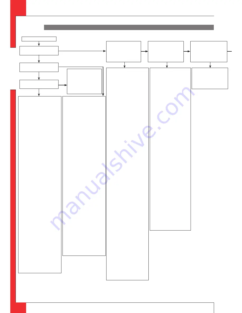
2.01 Can pilot be lit?

2.03 Only one spark?

2.02 Sparking?

2.09 Ignition procedure
-

Oval knob on gas control is
on "MAN". Set to "ON" and
restart.

Retarded ignition of main burner
Gas to main burner opens ca. 3-5
seconds after servo motor
operating the gas valve starts
running (sound of motor!). After
this the main burner is to ignite (at
least partially) within 10 seconds
and not with a firm noise WHOOF.
If not: no or delayed cross lighting
of main burner.
Hazardous situation. Stop ignition
procedure straight away and first
check for:
-

Position of logs or pebbles

-

Burner holes (locally)
blocked. Remove vermiculite
dust.

-

Vermiculite missing

-

Chips on burner

-

Vermiculite not distributed
evenly across burner(s)

PowerVent® (if present)
Consult PowerVent® installation
manual how to carry out the checks
below.
Check:
-

230V to fan controller unit
and fan

-

Silicon pressure
measurement hoses
swapped
leaking or barred

-

Pressure difference set too
high

-

Resistance of flue system too
high
adjustment of appliance
damper and air inlet guides)
flue length or number of
bends too large
dirty (e.g. cobwebs)

-

Operation of the fan

-

Operation of solenoid gas
valve

-

Operation of fan controller
unit

-

Operation of pressure
measurement gauge

2.11 No proper cross lighting
of main burner(s)                       
Go to box 2.09 and take
actions act as described for
'retarded ignition of main
burner'.                         

2.06 Pilot can be lit.
Does it stay alight?

2.10 Do(es) main burner(s)
ignite smoothly and across
its/their full length after after
first ignition by pilot burner?

2.08 Does main burner ignite
immediately?

2.04 Check:
Receiver
-

Replace missing, weak or
rechargeable batteries (not
enough power to open
thermoelectric valve)

Presence of gas on pilot burner
Check pilot on presence of gas at
normal ignition cycle or in Manual
Mode (turn oval knob on gas control
to MAN and keep safety shut off
valve opened with a screwdriver) and
ignite pilot with a lighter.
-

Pilot flame not on: Step 1

-

Pilot flame on: Step 2

Step 1: Pilot has no gas
-

Gas tap open?

-

Gas at gas control (line
pressure at measuring point on
gas control).

-

Check presence of gas at pilot
burner, by igniting in Manual
mode:
Turn oval knob on gas control
on MAN, open safety shut off
valve with a screwdriver and
try to ignite pilot with a lighter.
Not alight, then check the
following:

-

Blocking of pilot tube (kink or
dirt)

-

Gas flowing out of gas control?
(by loosening pilot tube at gas
control)

-

If not: check adjustment screw
pilot flame (under black cover):
sealing not to be broken.
Sealing broken: screw should
be fully open.

-

If this does not help: replace
gas control

                      
Step 2: Pilot has gas, but no
ignition
-

Electrode with 90° bended tip:
bend tip 1mm higher

-

Spark too weak (thin and
reddish). Act as if 'no spark' in
box 2.05 and perform actions
described for ignition cable
and ignition electrode.

-

Pilot flame too weak (dirty).
Remove injector (remove
gland nut and the pilot tube).
See that it does not fall away.
Clean with compressed air.

Rectify. Retry.

2.05 Check:

Ignition cable
-

Present and connected

-

Being free from metal parts or
concrete

-

Too long: cut away all
excessive length  at receiver
end, and reconnect

-

Shorting out to earth; replace
ignition cable.

-

Spark in wrong position

-

slide rubber sleeve on ignition
cable over ceramic of
electrode.

-

Replace electrode if
neccessary.

Ignition electrode
-

Straight electrode:

-

oxidation (roughen electrode
with file or sand paper)

-

position 4 mm from pilot
burner

-

Cracks in ceramic (not always
visible), replace electrode.

Thermocouple circuit interrupted
-

Check connection between:

-

thermocouple and interruptor

-

interruptor and gas control
Is it tight? (han half a
turn)

-

Black wires (yellow/red end)
not (well) connected in
thermocouple interruptor, in
right position on receiver (in
right position)

-

Thermocouple broken inside
thermocouple interruptor:
Replace.

-

Thermocouple interruptor
defective.
Check by screwing
thermocouple directly in gas
control and ignition in Manual
mode (see 2.04))

Starting procedure
After switching off/going out the
remote is locked for 120 sec. (older
versions 60 sec).
Wait 2 minutes before reigniting.

2.07 Check thermocouple system

Step 1: Check pilot flame and
thermocouple
-

Pilot flame too small

-

pilot dirty. Rectify (see 2.04)

-

check  for pilot gas tube
tightness

-

pilot tube kinks or dirt inside

-

line pressure too low

-

tip not in (correct!) pilot flame.
Bend into flame.

Step 2: Check circuit for
interruptions or short circuiting
-

thermocouple tight in
interruptor

-

interruptor tight in gas control

-

black wires (yellow/red end)

-

connected to inter
receiver

-

short circuitiong at interruptor

Step 3: Check receiver
Dismount black-red and -yellow
control cables from receiver and link
together. Ignite fire in Manual Mode
(see 2.04, light pliot with a
matchlight):
-

Pilot stays on: the receiver is
defective (replace) , and the
rest of the thermocouple
system is OK.

-

Pilot goes out: Step 4.

Step 4: Check thermocouple and
gas control
Screw thermocouple directly in gas
control and light in Manual Mode
(see 2.04, light pliot with a
matchlight):
-

Pilot stays on: Thermocouple
interruptor defective.

-

Pilot goes out:

-

thermocouple defective

-

thermo-electric device
defective

Go to step 5.

Step 5: Check thermocouple
Check thermocouple by replacing or
by measuring output voltage
(>5mV, with thermocouple
connected). See Appendix 3, fig. 42.

Step 6
If thermocouple is not the cause the
themo-electric device is defective.
Replace gas control.

8-Wire black control cable
-

8-wire cable between receiver
and gas control not
connected.

-

Poor contact of connector.
Check for pins on receiver not
being bended.

-

One of eight wires loose in
connector.

Check by pulling wire by wire at
both ends of cable)

yes

no

yes

yes

no

no

no

no

no

Fires with electronic ignition, fault finding: Ignition and burning

Appendix 1 diagnosis of malfunctions 

GB

UK

2.03a
-

Loosen and retighten
earthing screw on gas
control.

-

If this does not work:
replace receiver.

yes

Содержание G20

Страница 1: ...E n g l i s h Store this document in a safe place Circo Installation manual GB IE DRU15798 175417 EN 0213 2 G20 G25 G31 UK 959 044 01 UK ...

Страница 2: ...ncentric system 5 8 4 Connection existing chimney 5 9 Additional instructions 5 9 1 Placing the appliance 5 9 2 Gas connection 5 9 3 Placing the receiver 5 9 4 Placing the decoration ring 5 10 Glass pane 5 10 1 Removing glass pane 5 10 2 Placing glass pane 5 11 Setting the appliance 5 11 1 Air inlet guide 5 11 2 Restrictor slide 5 12 Placing the wood set 5 12 1 Wood set 6 Wireless remote control 6...

Страница 3: ... DRU Powervent system the DRU Smartvent system or the DRU Maxvent system you must carefully and fully read and use the accompanying installation manual as well prior to its installation The following symbols are used in the manual to indicate important information Ø Work to be performed Tip Suggestions and recommendations Caution You will need these instructions to prevent problems that might occu...

Страница 4: ...p it in an insulation blanket or any other material Ø make sure that combustible objects and or materials have a distance from the appliance of at least 500 mm Ø only use the accompanying wood pebble set and place it exactly as described Ø the space surrounding the pilot burner 2nd thermocouple or ionisation pins must remain free Ø make sure there is no dirt in gas pipes and connections Ø place a ...

Страница 5: ...fix the appliance to a platform or pallet Caution Heat resistant glass is a ceramic material Very small irregularities in the glass pane s cannot be avoided but are within the required quality standards Caution Keep plastic bags away from children In Appendix 2 Table 1 you can see which parts you should have after removing the packaging Ø Contact your supplier if you do not have all the parts afte...

Страница 6: ...erials Place the discharge pipes in such a way that situations with risk of fire can never occur Always place the appliance in front of a wall of non combustible and heat resistant material Always maintain a minimum distance between appliance and back wall if indicated in the dimensional drawing Appendix 3 fig 2 Take sufficient measures to prevent high temperatures of a possible wall behind the ch...

Страница 7: ...res of thermocouple 2 the ignition cable the flexible gas hose the aluminium pilot burner pipe and the type plate plus chain in the direction of the control hatch Caution Make sure there is no dirt in gas pipes and connections Avoid kinks in the pipes Caution Make sure the ignition cable cannot come into contact with other wires The data plate should remain attached to the chain Ø Set the height o...

Страница 8: ... using the appliance in order to prevent cracks 5 6 Placing the control hatch if applicable The control hatch also see paragraphs 5 4 and 5 5 is placed as low as possible in the chimney breast Caution The bottom of the control hatch may not be placed higher in the appliance than the burner surface A number of components are placed in the control hatch such as data plate gas control receiver belong...

Страница 9: ...spread an unpleasant smell during a longer period these are not suitable Place the flue gas discharge system as follows Ø Connect the pipe pieces or flexible SS discharge Ø You should only install the appliance in a well ventilated room which complies with the applicable national local and constructional installation regulations in order to guarantee sufficient air supply Tip When the appliance is...

Страница 10: ...e top row of Table 5 look for the required total vertical and or sloping pipe length 6 If you end up in a box with a letter the concentric system chosen by you is permissible 7 Use Table 6 to determine how the appliance should be adjusted 5 8 3 Placing the concentric system Caution Maintain a distance of at least 50 mm between the outside of the concentric system and the walls and or ceiling If th...

Страница 11: ... surrounding space is used to supply combustion air The following requirements apply when connecting to an existing chimney only allowed when used in combination with the special DRU chimney kit The installation regulation is also supplied the internal dimensions should be at least 150 x 150 mm the vertical length has a maximum of 12 metres the total horizontal pipe length may have a maximum lengt...

Страница 12: ...the left side panel C by grabbing it at the bottom and as far as possible to the right glass pane side and pulling it towards you Caution The side panels open and close by means of a snap on system S When opening and closing the panels you could experience some resistance That is normal Ø Put the receiver at the right location see Appendix 3 Fig 6 Ø Connect the receiver to the appliance according ...

Страница 13: ...le so it does not fall back Tip First fasten the left side of the front panel B when placing it back pull the front panel around the glass pane using the tensioning bolt T and then fasten the right side 5 11 Setting the appliance The appliance has to be set in such a way that it works correctly in combination with the discharge system used For that purpose a restrictor slide is placed and or an ai...

Страница 14: ...bed make sure the pilot burner and the surrounding space remain free see Appendix 3 fig 15 make sure thermocouple 2 and the surrounding space remain free see Appendix 3 fig 16 make sure the slot between and around the burners remains free make sure that the vermiculite s fine dust does not get on the burners 5 12 1 Wood set The wood set consists of vermiculite see Appendix 3 fig 17 chips see Appen...

Страница 15: ...order to avoid damaging the receiver Avoid formation of dust on or in the receiver cover it when performing work Place the receiver in its intended holder under the appliance or in the control hatch according to Appendix 3 fig 39 If you want to use an adapter only an adapter supplied by DRU will guarantee a proper operation of the receiver 6 1 1 Placing replacing the receiver s batteries Follow th...

Страница 16: ...he User Manual Ø If the pilot flame does not ignite repeat the ignition procedure until the pilot burner ignites consult the malfunction search diagram Appendix 1 if this does not happen after a few attempts Ø After igniting the pilot flame the main burner will ignite during the ignition procedure Ø Check whether the main burner continues to burn Ø If the main burner does not continue to burn repe...

Страница 17: ...the glass window is installed Use the malfunction search diagram Appendix 1 if the ignition of the main burner does not comply with the abovementioned requirements 7 4 Flame picture The flame picture can only really be assessed when the appliance has been burning for several hours Volatile components from paint materials etc which evaporate in the first hours will affect the flame picture Caution ...

Страница 18: ...nents the pilot burner malfunction search diagram Appendix 1 the space surrounding the pilot burner the glass pane s Caution Remove place the glass pane s as described in section 5 10 Remove the deposit on the inside of the glass pane s with a damp cloth or a non abrasive detergent such as copper polish or a ceramic hot plate cleaner Avoid remove fingerprints on the glass pane s since otherwise th...

Страница 19: ...or openers Ø Instruct the user about the appliance and the remote control Ø When the appliance is started for the first time point out that In order to avoid cracks in a chimney breast made of stone like materials or finished with plaster it should dry for at least 6 weeks prior to putting the appliance into operation When the appliance is stoked up for the first time volatile components evaporate...

Страница 20: ...weak dirty Remove injector remove gland nut and the pilot tube See that it does not fall away Clean with compressed air Rectify Retry 2 05 Check Ignition cable Present and connected Being free from metal parts or concrete Too long cut away all excessive length at receiver end and reconnect Shorting out to earth replace ignition cable Spark in wrong position slide rubber sleeve on ignition cable ov...

Страница 21: ... Check Gas supply Supply pressure does not drop away as main burner or other appliance lights causing pilot flame to shorten Burner pressure too high or too low Flames suffocating lack of air Dancing flames on burner Lack of combustion air Check flue system permissible proper flue terminal used Make should be DRU terminal correctly sited on roof or wall relative to obstructions integrity of fluein...

Страница 22: ...thin 20 seconds Then 2 short beeps and brief noise of servomotor to confirm that communication code was set succesfully Remote set Battery 9V empty see indication on display Several After switching off going out the remote set is locked for 120 sec older versions 60 sec Wait 2 minutes before reigniting 1 04 Check All appliances 8 wire cable between receiver and gas control not connected poor conta...

Страница 23: ...nual Decoration ring Restrictor slide Hexagonal nut M5 Washer 8 4 mm Sealing cap Socket spanner 8 mm Remote control with receiver 9V block battery Penlite battery AA type Compression fitting 15 mm x G3 8 Number 1x 1x 1x 1x 1x 2x 2x 2x 1x 1x 1x 4x 1x Table 1 Parts included with the delivery ...

Страница 24: ... Hs Nominal heat input Hi Nominal output Consumption Burner injector Consumption on low output Low setting injector Pilot burner injector Efficiency class Circo Free standing Closed combustion Concentric 150 100 Pilot flame with thermocouple yes no yes C11 C31 mbar kW kW kW L h mm L h mm Code G20 14 5 9 1 8 2 7 0 845 1x Ø 1 70 1x Ø 1 55 424 Ø 1 70 51 1 G25 18 2 8 2 7 4 6 0 913 1x Ø 1 70 1x Ø 1 55 ...

Страница 25: ...ertical pipe length 1 1 4 1 1 4 Total number of meters horizontal pipe length excluding wall terminal 0 2 0 3 Table 4 Conditions for setting the appliance See Figure 4 4 Air inlet guide YES NO Restrictor slide NO NO Distance of restriction in mm OPEN OPEN 1 minimum length 2 factory setting Permissibility and conditions concentric system with wall terminal G20 G25 G31 ...

Страница 26: ...etermining permissibility concentric system G20 G25 G31 Total number of meters horiz pipe length Total no of meters vertical and or sloping pipe length no bends 2 bends 3 bends 4 bends 5 bends Situation is not permissible minimum length Situation A B C D Air inlet guide NO YES YES YES Table 6 Conditions for the adjustment of the appliance with a roof terminal Restrictor slide NO YES YES YES Distan...

Страница 27: ...E n g l i s h INSTALLATION MANUAL Appendix 3 Figures UK 1041 5 430 79 5 35 150 100 475 372 5 442 5 605 172 38C 1776 Min 40 mm Min 500 mm 38c 1777 2 1 4a 4b ...

Страница 28: ...E n g l i s h INSTALLATION MANUAL UK 38c 1780 1 B Q T 38c 1778 S C D 4x K 38c 1779 7 5 6 ...

Страница 29: ...E n g l i s h INSTALLATION MANUAL UK 38c 1781 1 G A H P 38c 1783 38c 1782 E F R 6x 9 8 10 ...

Страница 30: ...E n g l i s h INSTALLATION MANUAL UK A A 38c 1784 A A 38c 1785 G H I L 12 11 ...

Страница 31: ...E n g l i s h INSTALLATION MANUAL UK 38c 1786 L J R 38c 1787 14 13 ...

Страница 32: ...E n g l i s h INSTALLATION MANUAL UK 38P 0265 38P 0266 38p 0022 38p 0023 3 8 P 0 1 1 3 38P 0273 19 15 16 20 17 18 ...

Страница 33: ...E n g l i s h INSTALLATION MANUAL UK A B C D 38P 0267 0 38P 0268 A 38P 0269 B 22 21 23 ...

Страница 34: ...E n g l i s h INSTALLATION MANUAL UK 38P 0270 C 38P 0271 D 25 24 ...

Страница 35: ...E n g l i s h INSTALLATION MANUAL UK 38c 1788 38p 0179 38p 0181 5mV 38p 0182 A A 28 7 B SECTION A A SCALE 1 20 15 25 38C 1663 0 42 38 39 43 40 41 ...

Страница 36: ...E n g l i s h DRU Verwarming B V The Netherlands Postbus 1021 NL 6920 BA Duiven Ratio 8 NL 6921 RW Duiven UK ...

Отзывы: