background image

  Document: Service Manual 

Description: Treadmill 

Model: M7 LED 

Page: 57 of 60 


57 

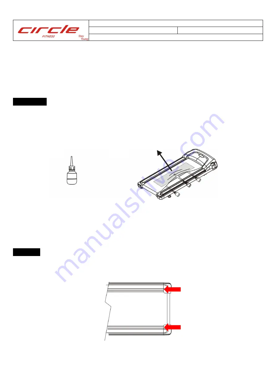
6.3 How to spray silicone on deck


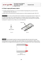
1). Find the silicone bottle (Fig 5.3-1). It put into hardware kit package when you purchase this 

treadmill, and open the carton box. 

2). Spray silicone on treadmill deck evenly, the spray area is like the drawing showing. (Fig 5.3-2) 
 

IMPORTANT!


You must stop the treadmill belt completely before spraying the silicone. Failure to do 

so could cause injury such as cutting your hand on the edge of the belt and crushing your fingers 
between the rear roller and the belt. Do NOT spray too much silicone on the deck. It can cause the 
running belt to slip when in use if there is too much lubrication. 


WARNING!

 The running belt should be centered and adjusted within the area which has been 

indicated by the arrows on right roller cover and left roller cover. The running belt could be worn or 
damaged if the running belt travels beyond this scope. The running belt travel area is showing below: 


Fig 5.3-1 


Silicone bottle     

Spray area 


Fig 5.3-2 

Fig 5.3-3 

(Running Belt Travel Area) 

Содержание M7

Страница 1: ......

Страница 2: ... GUIDE 20 5 1 Toolkits Components Required 20 5 2 Panel of Console Replacement 21 5 3 Membrane and Overlay Replacement 23 5 4 M7 Treadmill Side Rails Replacement 26 5 5 Running Belt Replacement 28 5 6 Drive Belt Replacement 35 5 7 Drive Motor Replacement 41 5 8 Inverter Replacement 44 5 9 Emergency Stop Replacement 47 5 10 Hand pulse Set Replacement 49 5 11 Incline Motor Replacement 52 6 MAINTENAN...

Страница 3: ...rovides this manual primarily to assist qualified service technicians in the service of the appliance Should the reader have any questions or concerns which have not been satisfactorily addressed please call send an e mail message or write to the CIRCLE FITNESS Technical Support Department for assistance Tel 886 4 2359 1000 259 Fax 886 4 3505 5801 Email chris chang pandfbrother com CIRCLE FITNESS ...

Страница 4: ...Document Service Manual Description Treadmill Model M7 LED Page 4 of 60 4 1 INFORMTION FOR COMPONENTS SYSTEM 1 1 System wiring diagram ...

Страница 5: ...S232 P6 G12 GND P3 EXG P7 SAFETY KEY P4 WK_UP Wireless receiver Jk8 P1 sensor input P2 VCC P3 GND SAFE KEY Jk4 P1 Driver EN P2 VDD STOP key Jk14 P1 KeyBoard S5 P2 KeyBoard D2 FAN Jk1 P1 PWM 0 12V P2 VDD Hand Pulse Jk7 P1 Left reference electrode P3 Right signal electrode P2 Left signal electrode P4 Right reference electrode Quick shift SPEED J5 P1 SPD P2 COM P3 SPD ...

Страница 6: ...D2 Rolling Interval 2 7 X 8 D3 Valley Random 3 8 X 9 D4 Fat Burn Fitness Test 4 9 X 10 D5 Ramp H R C 5 0 Enter MEMBRANE KEYBOARD R Right 8P 1 S6 2 S7 3 S8 4 S9 5 D6 Inc 8 Spd 4 Cool Down Inc Up 6 D7 Inc 6 Spd 6 Fan Inc Down 7 D8 Inc 4 Spd 8 Stop Spd 8 D9 Inc 2 Spd 10 Start Spd 1 3 Inverter Please replace to new version inverter if it is a old version one Old version inverter New version inverter W...

Страница 7: ... start again still show OC Replace the running belt or deck if always happen while running 2 3 Error message OE The operation voltage too high maybe happen at high incline level and heavy load exercising contact manufacture for solution 2 4 Error message PrEr The inverter Flash memory problem replace the inverter 2 5 Error message EEr The inverter EEPROM problem replace the inverter 2 6 Error mess...

Страница 8: ...ing already too high have to lubricate or replace running belt or deck 2 9 Error message OL The motor current overloads over 110 few minutes have to replace the running belt or deck 2 10 Error message OL1 The motor current overloads over 150 have to replace the running belt or deck 2 11 Error message ntcF The thermo sensor abnormal replace inverter 2 12 Error message LF The motor wires did not con...

Страница 9: ...w Err6 Reset power OFF ON Does incline motor moving Yes No Incline motor jammed to eliminate jam problem then check the inverter shall be the new version refer to 1 3 and console firmware version great than V1 05 if not replace or update it Is it move about 1 2 then stop Yes No Press Start then set incline to 15 System operating normal but please check the inverter shall be the new version and con...

Страница 10: ...2 16 Error message ESP Inverter emergency protection Show ESP Open motor cover Dis connect ESP wire from inverter Short circuit the ESP terminal with a screw Metal Reset AC power and wait 5 seconds Is it still show ESP Yes Replace inverter No Replace console communication wire ...

Страница 11: ...rror message UArt Communication time out console can not communication with inverter over 10 seconds Open motor cover Switch ON the power Does communication lamp where on the inverter flash before console show UArt Flash No Flash Replace inverter Replace console or communication wire ...

Страница 12: ... newest version great than V1 05 No Set incline to level 15 then set to level 0 Does the incline work abnormal and stop then show Err1 Yes No System operating normal but please check the inverter shall be the new version and console firmware version great than V1 05 if not replace or update it The incline motor jammed or input power too low the input power shall over 90V 110V system 200V 220V syst...

Страница 13: ... no any error message show on time window To check the motor wires connection or replace inverter 2 21 Console work normally but motor cannot move To check the motor wires connection same as upon or replace inverter Does lamp lights up on inverter Console no power Open motor cover Yes No Replace inverter Replace console Check motor wires connection ...

Страница 14: ...enter engineer mode Reset power OFF ON Press Enter till dot matrix show IO Press incline up to drive incline motor Does incline motor move Yes No Incline motor jammed have to eliminate and try again Is parameter can be increase up over 700 when motor move up Press incline up again to stop the incline motor while parameter over 700 Yes System operating normal No Replace incline motor No Replace inv...

Страница 15: ...eys test mode dot matrix show KEY each key has their own code when press a key the code show as below press Enter to next test mode 3 1 1 5 Test mode Press Start can drive motor press speed keys to change speed press incline keys to drive incline motor press Enter back to 4 1 1 1 retest press and hold RESET CLEAR then press Quick Start 3 seconds to exit Key Code Key Code Key Code Key Code Target 0...

Страница 16: ...TING one time then show ON press or change to OFF press ENTER to next setting 3 2 2 5 MIN SPEED Dot matrix show SET MIN SPEED THEN PRESS ENTER SPEED window show value press or to set value press ENTER to next setting 3 2 2 6 MAX SPEED Dot matrix show SET MAX SPEED THEN PRESS ENTER SPEED window show value press or to set value press ENTER to next setting 3 2 2 7 MAX ELEVATION Dot matrix show SET MA...

Страница 17: ...TER INFORMATION AND EXTERNAL CONTROL 4 1 External control Key Pad usage 4 1 1 External control Key Pad appearance KP 208 and connection 4 1 2 Monitor mode and operation Output frequency Frequency setting Output voltage PN Voltage Output current void void void Incline setting void void ...

Страница 18: ...control inverter by External control Key Pad 4 1 3 1 Start Stop Fast Slow Start Stop Fast Slow Press PROG change to function setting at any display mode press to show F_001 Press FUN DATA enter the F_001 setting default value is 0 Press change value to 1 Press FUN DATA to save and exit ...

Страница 19: ...Document Service Manual Description Treadmill Model M7 LED Page 19 of 60 19 4 1 3 2 Incline control Parameter setting Incline parameter Incline UP Incline Down Monitor mode Monitor mode 9 ...

Страница 20: ...ice Manual Description Treadmill Model M7 LED Page 20 of 60 20 5 PART PLACEMENT GUIDE 5 1 Toolkits Components Required Open End Wrench T type Wrench Allen Wrenches Belt Tension Gauge Screw Driver Combination Wrench ...

Страница 21: ... 5 2 Panel of Console Replacement STEP 1 Remove the 7 screws to disassemble the Lower Console Cover via screw driver STEP 2 Remove the screws under the right left handlebar and remove the Lower Console Cover STEP 3 Remove the screws under the Upper Console Cover to disassemble ...

Страница 22: ...the mounting screws on PCB and replace the New PCB on right position Secure the mounting screws on PCB and plug the Flexible flat cable back on PCB STEP 6 Plug the cables and wires on PCB of Console and put the Upper Console Cover back Secure the 6 mounting screws under the Upper Console Cover to assemble Put the Lower Console Cover back and secure the 9 screws for complete ...

Страница 23: ... 3 Membrane and Overlay Replacement STEP 1 Remove the 7 screws to disassemble the Lower Console Cover via screw driver STEP 2 Remove the screws under the right left handlebar and remove the Lower Console Cover STEP 3 Remove the screws under the Upper Console Cover to disassemble ...

Страница 24: ...g flexible flat cable of membrane for PCB Remove the faulty membrane and overlay on Console Clearing the Upper Console surface with alcohol to remove any left over adhesive STEP 6 Insert the flexible flat cable of membrane into the hole of the upper console and plug it in Remove the protective film from the back of the membrane and paste it ...

Страница 25: ...rotective film from the back of the Overlay and paste on the console STEP 8 Plug the cables and wires on PCB of Console and put the Upper Console Cover back Secure the 6 mounting screws under the Upper Console Cover to assemble Put the Lower Console Cover back and secure the 9 screws for complete ...

Страница 26: ... 60 26 5 4 M7 Treadmill Side Rails Replacement STEP 1 Remove the roller cover by unscrewing the 4 screws on both sides STEP 2 Remove the end cap set plate by unscrewing the 4 screws on both sides STEP 3 Release 8 bolts underneath side rail via M5 Wrench without loosening ...

Страница 27: ...left and right side rails off from the treadmill to replacement Put the new left and right side rails back and secure 8 screws STEP 5 Locate the end cap set plate and secure 4 screws on both sides Put the roller cover back to position and secure screws on both sides via screwdriver for complete ...

Страница 28: ...t STEP 1 Remove the Motor Covers by loosing 4 screws Remove the 4 screws on Right Left console mast via screwdriver STEP 2 Loosen 2 Tension screws on the rear roller via Allen wrench Caution Don t remove the Tension Screws from Treadmill STEP 3 Release 4 motor mounting screws on motor plate via M8 wrench ...

Страница 29: ...ge 29 of 60 29 STEP 4 Release 2 adjustment screws on the front and rear motor boundary via two M14 wrenches STEP 5 Push the motor to front roller and split the belt from the motor output shaft pulley STEP 6 Remove 2 front roller mounting screws using an M6 Wrench ...

Страница 30: ...Page 30 of 60 30 STEP 7 Lift up the front roller on pulley side and remove the drive belt from the front roller STEP 8 Remove the roller cover by unscrewing the 4 screws on both sides STEP 9 Remove the end cap set plate by unscrewing the 4 screws on both sides ...

Страница 31: ...el M7 LED Page 31 of 60 31 STEP 10 Release 8 bolts underneath side rail via M5 Wrench without loosening STEP 11 Slide out left and right side rails off from the treadmill to replacement STEP 12 Remove 2 rear roller tensioning screws using an M6 Wrench ...

Страница 32: ... roller from the running belt STEP 15 Remove running deck from one side and replace new running belt Be aware of sharp edge of running deck wearing gloves at work is suggested To install new running belt place new belt with transverse direction and insert new deck through the running belt Install new running belt and deck locate on deck cushion and rubber cushion Lock and secure the deck with deck...

Страница 33: ...ront mounting screws via M6 wrench STEP 17 Place and install motor drive belt as M7 drive belt replacement instruction STEP 18 Put the left and right side rails back and secure 8 screws STEP 19 Locate the end cap set plate and secure 4 screws on both sides STEP 20 Put the roller cover back to position and secure screws on both sides via screwdriver STEP 21 Secure 2 tensioning screws on the rear ro...

Страница 34: ...ole masts back and secure 4 screws to assemble STEP 23 To properly tension a new running belt using M6 torque wrench 45 kgf cm and Allen wrench Rotating the tension bolts clockwise until heard the click of torque wrench Start the treadmill and run it at 10 km hr Counting adjusting belt until the belt maintain centered and it does not move to one side or another within 5 minutes ...

Страница 35: ... STEP 1 Remove the Motor Covers by loosing 4 screws Remove the 4 screws on Right Left console mast via screwdriver STEP 2 Loosen 2 Tension screws on the rear roller via Allen wrench Caution Don t remove the Tension Screws from Treadmill STEP 3 Release 4 motor mounting screws on motor plate via M8 wrench ...

Страница 36: ...ge 36 of 60 36 STEP 4 Release 2 adjustment screws on the front and rear motor boundary via two M14 wrenches STEP 5 Push the motor to front roller and split the belt from the motor output shaft pulley STEP 6 Remove 2 front roller mounting screws using an M6 Wrench ...

Страница 37: ...e front roller STEP 8 Install the new drive belt H041013 000 660J STEP 9 Checking pulley groove in V Belt Drive The motor pulley The V belt located the motor pulley and the sheave Grooves without gap The front roller pulley The V belt located the front roller pulley and the sheave Grooves has 1 grooves on each edge The motor pulley The front roller pulley ...

Страница 38: ... screws on the front roller STEP 11 Place and install motor alignment fixture Secure the motor fixture screw STEP 12 Tighten screw 2 on adjustment rod 1and release screw 1 which closes motor side for adjustment via M14 M17 wrench Secure the screw2 to adjust the belt tension The tension value is 240 Hz ...

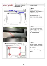
Страница 39: ...ews on adjustment rod 2 using M17 and M14 wrench The tension value is 206 216Hz 500 550N STEP 14 After the rod screws are locked confirm the motor alignment fixture is parallel to the motor plane STEP15 Secure 4 motor mounting screws on motor plate via M8 wrench Remove the motor alignment fixture ...

Страница 40: ...ts back and secure 4 screws on motor cover to assemble STEP 17 To properly tension a new running belt using M6 torque wrench 45 kgf cm and Allen wrench Rotating the tension bolts clockwise until heard the click of torque wrench Start the treadmill and run it at 10 km hr Counting adjusting belt until the belt maintain centered and it does not move to one side or another within 5 minutes ...

Страница 41: ...tor Replacement STEP 1 Remove the Motor Covers by loosing 4 screws Remove the 4 screws on Right Left console mast via screwdriver STEP 2 Release 4 motor mounting screws on motor plate via M8 wrench STEP 3 Release 2 adjustment screws on the front and rear motor boundary via two M14 wrenches ...

Страница 42: ...n motor adjustment plate STEP 5 Install the drive belt Checking pulley groove in V Belt Drive The motor pulley The V belt located the motor pulley and the sheave Grooves without gap The front roller pulley The V belt located the front roller pulley and the sheave Grooves has 1 grooves on each edge STEP 6 Place and install motor alignment fixture Secure the motor fixture screw The motor pulley The ...

Страница 43: ...ews on adjustment rod 2 using M17 and M14 wrench The tension value is 206 216Hz 500 550N STEP 8 After the rod screws are locked confirm the motor alignment fixture is parallel to the motor plane STEP 9 Secure 4 motor mounting screws on motor plate via M8 wrench Remove the motor alignment fixture ...

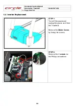
Страница 44: ... Treadmill Model M7 LED Page 44 of 60 44 5 8 Inverter Replacement STEP 1 Turn off the power and unplug the power cord from the Treadmill Remove the Motor Covers by losing the screws STEP 2 Remove the 2 screws via the Philips screwdriver ...

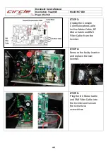
Страница 45: ... Unplug the Console Communication Cable Incline Motor Cable DC Motor Cable and EMI Filter Cable from the Inverter STEP 4 Remove the faulty Inverter and replace the new Inverter STEP 5 Plug the DC Motor Cable and EMI Filter Cable into the Inverter and secure the screws via screwdriver ...

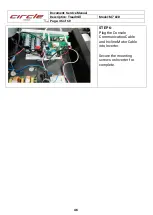
Страница 46: ...ment Service Manual Description Treadmill Model M7 LED Page 46 of 60 46 STEP 6 Plug the Console Communication Cable and Incline Motor Cable into Inverter Secure the mounting screws on Inverter for complete ...

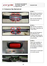
Страница 47: ...a M3 wrench Remove the Emergency Stop Lower Cover STEP 2 Remove the 4 screws on Emergency Stop Base via screw driver Remove the Emergency Stop Base Service Package and Unplug the Emergency Stop Cable to disassemble STEP 3 Place and install the on Emergency Stop Base and plug the Emergency Stop Cable into the Base to assemble Secure the 4 screws part 2 via M3 wrench ...

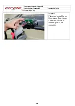
Страница 48: ...Document Service Manual Description Treadmill Model M7 LED Page 48 of 60 48 STEP 4 Place and install the on Emergency Stop Lower Cover and secure 4 screws part 1 for complete ...

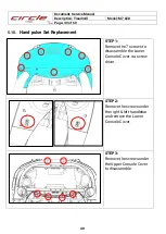
Страница 49: ... 5 10 Hand pulse Set Replacement STEP 1 Remove the 7 screws to disassemble the Lower Console Cover via screw driver STEP 2 Remove the screws under the right left handlebar and remove the Lower Console Cover STEP 3 Remove the screws under the Upper Console Cover to disassemble ...

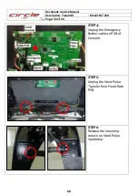
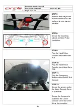
Страница 50: ...escription Treadmill Model M7 LED Page 50 of 60 50 STEP 4 Unplug the Emergency Button cable on PCB of Console STEP 5 Unplug the Hand Pulse Transfer from Heart Rate PCB STEP 6 Release the mounting screws on Hand Pulse Handlebar ...

Страница 51: ...ure the mounting screws on Hand Pulse Handlebar STEP 9 Plug the Hand Pulse Transfer into Heart Rate PCB STEP 10 Plug the Hand Pulse Transfer back Heart Rate PCB STEP 11 Plug the Emergency Button cable back PCB of Console STEP 12 Secure the screws under the Upper Console Cover to assemble Secure the 9 screws to assemble the Lower Console Cover via screw driver for complete ...

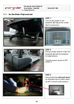
Страница 52: ... STEP 1 Turn on the power of the treadmill and adjust the incline level to maximum STEP 2 Place a sturdy objects under the treadmill and life the treadmill to keep balance Turn the power switch to OFF position STEP 3 Unscrew bottom bolt and screw on threaded rod of incline motor via M17 wrench and remove it ...

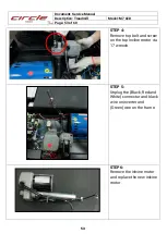
Страница 53: ...D Page 53 of 60 53 STEP 4 Remove top bolt and screw on the top incline motor via 17 wrench STEP 5 Unplug the Black Red and White connector and black wire on inverter and Green wire on the frame STEP6 Remove the inlcine motor and replace the new inlcine motor ...

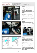
Страница 54: ...matically if its not at the zero position VR on incline 0 STEP8 Install the incline motor and reattach to secure the top bolt screw and washers release 1 4 turn for better movement STEP9 The gap between Mainframe and the Cushion on incline motor will be 3mm to 5mm NOTE If this step is not done the incline motor might get jammed when it is powered on by the inverter and console You may refer the fo...

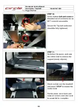
Страница 55: ...otor via M17 wrench to assemble Secure the Top bolt and screw should be fully tightened STEP11 Switch on the power and raise the incline level to remove the support sturdy objects Check no items on the treadmill and press STOP to restore the incline level Put the motor cover back and secure 2 screws on motor cover to assemble for complete ...

Страница 56: ...the finger to press the selection buttons on the console Use a 100 cotton cloth lightly moistened with water and a mild liquid cleaning product to clean Other fabrics including paper towels may scratch the surface Do NOT use ammonia or acid based cleaners Brush away any wax deposits from the deck and belt area 6 2 Running belt and running deck lubrication Regular maintenance is necessary for best ...

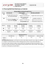
Страница 57: ...o could cause injury such as cutting your hand on the edge of the belt and crushing your fingers between the rear roller and the belt Do NOT spray too much silicone on the deck It can cause the running belt to slip when in use if there is too much lubrication WARNING The running belt should be centered and adjusted within the area which has been indicated by the arrows on right roller cover and le...

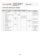
Страница 58: ... Frame Wipe Visual Inspection 3 Surface of the Running area Clean dust Visual Inspection 4 Power Cord Visual Inspection 5 Overlay Wipe Visual Inspection 6 Handlebar Wipe Visual Inspection 7 Handlebar screws Visual Inspection 8 Front Roller Groove Wipe Visual Inspection 9 Rear Roller Visual Inspection 10 Safety Key Wipe 11 Drive Belt Wipe Visual Inspection 12 Running belt tension Visual Inspection ...

Страница 59: ...3month 6000km 6month 9000km 9month 12000km 12month 15000km 15month M7 15ml 15ml 15ml 15ml 15ml M7 no silicone oil required no silicone oil required Detect motor current no silicone oil required no silicone oil required Motor Current List New Machine Slight wear Moderate wear Need exchange Output current 5 6 7 5 7 5 Running belt deck is worn It will cause the motor current input current to be too h...

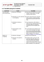
Страница 60: ...nnector point insert PINs C Check fuse near on off switch is worked or not if worked push it back and restart again if work please maintenance the running belt and deck D Turn off power then open the motor cover turn on the power and check the console power pilot lamp LED2 where on the interface PCB it shall be light completely if not replace it Refer to Chapter 5 3 1 on next page Display not comp...

Отзывы: