GM-1000 Series | User Manual
90
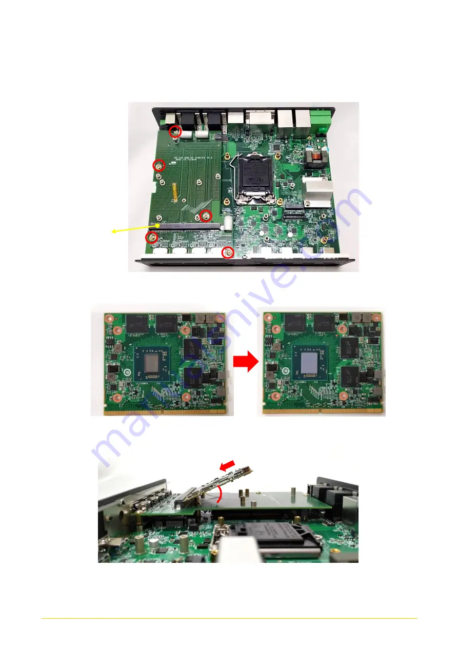
3.
Insert the MXM carrier board vertically to the connector on the system mainboard, and
fasten the screws as indicated below.
4.
Place the thermal pad on the chip of MXM Module.
5.
Insert the MXM Module into the slot on the MXM carrier board at 45 degrees.
This slot is used to connect
an MXM Module
45°
Содержание GM-1000 Series
Страница 13: ...GM 1000 Series User Manual 13 Chapter 1 Product Introductions ...
Страница 20: ...GM 1000 Series User Manual 20 1 7 Mechanical Dimension ...
Страница 21: ...GM 1000 Series User Manual 21 Chapter 2 Switches Connectors ...
Страница 22: ...GM 1000 Series User Manual 22 2 1 Location of Switches and Connectors 2 1 1 Top View ...
Страница 23: ...GM 1000 Series User Manual 23 2 1 2 Bottom View ...
Страница 33: ...GM 1000 Series User Manual 33 Chapter 3 System Setup ...
Страница 52: ...GM 1000 Series User Manual 52 Chapter 4 BIOS Setup ...
Страница 74: ...GM 1000 Series User Manual 74 Chapter 5 Product Application For CMI DIO01 Only ...
Страница 77: ...GM 1000 Series User Manual 77 ...
Страница 84: ...GM 1000 Series User Manual 84 Reference Input Circuit Reference Output Circuit ...
Страница 85: ...GM 1000 Series User Manual 85 Chapter 6 Optional Modules Accessories Pin Definitions and Settings ...


