CS
-
100
-
P2100 Series | User Manual
97
6.4 VESA Mount
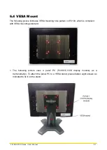
The following picture indicates VESA mounting hole pattern on P2100, which is compliant
with VESA mounting standard.
1.
The following picture uses a panel PC (P2100+CV/CS display module) as a
demonstration. To attach the panel PC to a VESA stand, please fasten eight screws as
indicated to fix it on the stand.
Содержание CS-100/P2100 Series
Страница 14: ...CS 100 P2100 Series User Manual 14 Chapter 1 Product Introductions ...
Страница 26: ...CS 100 P2100 Series User Manual 26 Chapter 2 Switches Connectors ...
Страница 27: ...CS 100 P2100 Series User Manual 27 2 1 Location of Switches and Connectors 2 1 1 Top View 2 1 2 Bottom View ...
Страница 36: ...CS 100 P2100 Series User Manual 36 Chapter 3 System Setup ...
Страница 60: ...CS 100 P2100 Series User Manual 60 ...
Страница 62: ...CS 100 P2100 Series User Manual 62 Chapter 4 BIOS Setup ...
Страница 81: ...CS 100 P2100 Series User Manual 81 Chapter 5 Product Application ...
Страница 84: ...CS 100 P2100 Series User Manual 84 ...
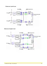
Страница 91: ...CS 100 P2100 Series User Manual 91 Reference Input Circuit Reference Output Circuit ...
Страница 92: ...CS 100 P2100 Series User Manual 92 Chapter 6 Optional Modules Accessories Pin Definitions and Settings ...


