13
MAINTENANCE
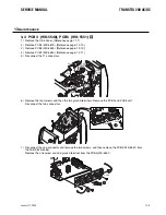
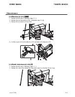
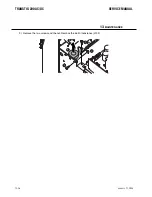
4 ) Disconnect the one connector.
Remove the two screws and one ground terminal and remove the PCB17 unit.
5 ) Remove the two screws and remove the S1 Bus Bar from the PCB17 (WK-4917).
3.16 PCB18 (WK-5861)
V
1 ) Remove the Side Panel. [Reference page: 11-1]
2 ) Remove the four screws and then remove the four cables.Remove the two screws. Remove the PCB18
(WK-5861).
1
2
2
3
4
CN1
1
2
1
1
2
2
January 17, 2008
13-21
SERVICE MANUAL
TRANSTIG 200 AC/DC
January 17, 2008
13-21
Содержание TRANSTIG 200 AC/DC
Страница 8: ...THIS PAGE LEFT INTENTIONALLY BLANK ...
Страница 20: ...TRANSTIG 200 AC DC SERVICE MANUAL 2 6 January 17 2008 NOTES ...
Страница 34: ...5 2 January 17 2008 TRANSTIG 200 AC DC SERVICE MANUAL NOTES ...
Страница 58: ...January 17 2008 11 2 TRANSTIG 200 AC DC SERVICE MANUAL NOTES ...
Страница 74: ...TRANSTIG 200 AC DC SERVICE MANUAL January 17 2008 12 16 THIS PAGE LEFT INTENTIONALLY BLANK ...
Страница 111: ...THIS PAGE LEFT INTENTIONALLY BLANK SERVICE MANUAL TRANSTIG 200 AC DC January 17 2008 13 37 ...
Страница 122: ...A 11 January 17 2008 TRANSTIG 200 AC DC SERVICE MANUAL NOTES ...
Страница 126: ......


