CIGWELD Transmig 210 Скачать руководство пользователя страница 13

Transmig 210, 250, 310, 330 

Page 14 of 31 DOC No:  MIGTRN0001

Date: 14/09/98 Issue No:  2

4. SET UP FOR COMPACT TRANSMIGS

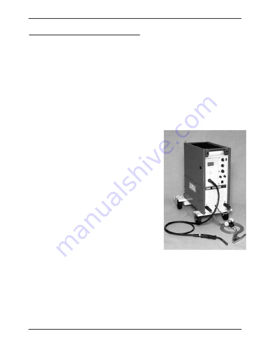
Refer to Figure 4 for the plant setup of a compact Transmig.

a) Remove all packaging materials.

b) Fit the fixed and swivel wheels to the Power Source.

WARNING 2: To obtain adequate air flow and cooling for  the Power Source components, the

four wheels must be fitted.  Alternatively, the Power Source may be raised
140mm from the floor using supports that do not restrict airflow.

c) Connect the work lead to the negative welding terminal (-) [positive welding terminal (+)

for flux cored wire].

d) Connect the 

TORCH

 lead to the positive welding terminal (+) [negative welding terminal

(-) for flux cored wire].

e) Position a gas cylinder on the rear tray and lock securely to the Power Source cylinder

bracket with the chain provided.  If this arrangement is not used then ensure that the gas
cylinder is secured to a building pillar, wall bracket or otherwise securely fixed in an
upright position.

f) Fit the gas Regulator/Flowmeter to the gas

cylinder.

g) Connect the gas hose from the rear of the Power

Source to the Flowmeter outlet.

h) Two dual groove feed rollers are supplied as

standard with the plant.  These can accommodate
0.6, 0.8, 0.9 and 1.2 diameter hard wires.  Select
the roller required with the chosen wire size
marking facing outwards.

i) Fit the electrode wire spool to the wire reel hub

located behind the wire compartment door.
Ensure that the drive dog-pin engages the mating
hole in the wire spool.  Push the 'R' clip into place
to retain the wire spool securely.  The wire should
feed from the bottom of the spool.

j) Fit the TWECO MIG torch to the wire feed unit

by releasing the torch locking screw in the brass
torch adaptor and pushing in the torch fitting until
the plastic torch casing meets the brass adaptor.
Tighten the torch locking screw securely.  Also
ensure that the adjacent black knurled screw in the
wire feeder casting is securely tightened.  Remove the contact tip from the torch.

k) Connect the two black torch trigger leads to the torch trigger terminals.

l) Lift up the wire feeder pressure lever and pass the electrode wire through the inlet guide,

between the rollers, through the outlet guide and into the torch.

m) Lower the pressure lever and with the torch lead reasonably straight, feed the wire through

the torch.  Fit the appropriate contact tip.

CAUTION 3: The electrode wire will be at welding voltage potential whilst it is being fed

through the system.

Figure 4 - Compact Transmig Setup

Содержание Transmig 210

Страница 1: ...ower Source 704832 Remote Power Source 704808 TRANSMIG 250 Compact Power Source 704833 Remote Power Source 704809 2R TRANSMIG 210 250 Wirefeeder 704975 TRANSMIG 310 Compact Power Source 704836 TRANSMI...

Страница 2: ...and Features 16 6 1 Indicator Light 16 6 2 Standby Coarse Voltage Control Switch and Fine Voltage Control Switch 16 6 3 Digital Ammeter and Voltmeter Standard for Transmig 330 Only 17 6 4 Torch Polar...

Страница 3: ...feeder 23 8 2 Position of MIG Torch 23 8 3 Distance from the MIG Torch Nozzle to the Work Piece 23 8 4 Travel Speed 23 8 5 Stitch Welding Operation 23 8 6 Spot Welding Operation 24 9 ROUTINE MAINTENAN...

Страница 4: ...actory fitted Mains supply leads fitted to the Transmig Power Sources 13 Table 2 Mains supply lead sizes for alternative Mains supply voltages 13 Table 3 MIG torch gas diffusers 19 Table 4 MIG torch c...

Страница 5: ...Figure 3 Voltage settings for Transmig 310 330 13 Figure 4 Compact Transmig Setup 14 Figure 5 Remote Transmig Setup 15 Figure 6 Compact Transmig controls 16 Figure 7 Remote Transmig controls 16 Figur...

Страница 6: ...e instructions thoroughly before using your Transmig 1 1 Duty Cycle The rated duty cycle of a welding Power Source is the operating time it may be used at its rated output current with out exceeding t...

Страница 7: ...eriod 5 minutes or 10 minutes 5 minutes or 10 minutes Number of Output Voltage Values 16 16 Wire Size Range 0 6 0 9 Hard 0 9 1 2 Soft 0 6 0 9 Hard 0 9 1 2 Soft Operating Temperature Range 0 C to 40 C...

Страница 8: ...tes 5 minutes or 10 minutes Number of Output Voltage Values 24 24 Wire Size Range 0 6 1 2 Hard 0 9 1 2 Soft 0 6 1 2 Hard 0 9 1 2 Soft Operating Temperature Range 0 C to 40 C 0 C to 40 C Primary input...

Страница 9: ...Flux Cored 0 8 0 9 1 2 Operating Temperature Range 0 C to 40 C Wire Spool Size 15Kg Maximum Spot Time Range 0 to 2 5 Seconds Stitch ON Time 0 to 2 5 Seconds Stitch OFF Time 0 to 2 5 Seconds Burnback...

Страница 10: ...nterconnection Extension 4 4 704465 8 M Interconnection Extension 4 717162 TWECO No 2 torch 3 6M adaptor 704915 required 4 4 4 4 4 4 717201 TWECO No 4 torch 3 6M adaptor 704915 required 4 4 4 4 4 4 70...

Страница 11: ...ording to the following guidelines a In areas free from moisture and dust b Ambient temperature 0 C to 40 C c In areas free from oil steam and corrosive gases d In areas not subjected to abnormal vibr...

Страница 12: ...ly Voltage Requirements The Power Sources are suitable for the following Mains supply voltages Mains Supply Voltage Setting Mains Supply Lead Size Mains Outlet Size Fuse Size Machines Duty Cycle Expor...

Страница 13: ...are supplied as standard with the plant These can accommodate 0 6 0 8 0 9 and 1 2 diameter hard wires Select the roller required with the chosen wire size marking facing outwards i Fit the electrode w...

Страница 14: ...eeder unit to the Flowmeter outlet d Two dual groove feed rollers are supplied as standard with the plant These can accommodate 0 6 0 8 0 9 1 0 and 1 2 diameter hard wires Select the roller required w...

Страница 15: ...Light The indicator light is provided to indicate when the Transmig is connected to the Mains supply voltage WARNING 3 When the light is lit the machine is connected to the Mains supply voltage and th...

Страница 16: ...ss electrode wire If in doubt consult the manufacturer of the electrode wire for the correct polarity 6 5 Positive and Negative Welding Terminals Welding current flows from the Power Source via heavy...

Страница 17: ...OT TIME knob controls the welding or ON time whilst stitch welding 6 11 Dwell Timer Compact Models 2R Wirefeeder Only The DWELL TIME knob controls the interval or OFF time whilst stitch welding 6 12 M...

Страница 18: ...e brake Correct adjustment will result in the reel circumference continuing no further than 20mm after release of the Torch trigger switch The electrode wire should be slack without becoming dislodged...

Страница 19: ...7 EL22A50 12 7 EL22CT50 12 7 EL22A50F 12 7 EL22CT50F 12 7 EL22I50P 12 7 EL22CT50P 15 9 EL22A62 15 9 EL22CT62 15 9 EL22A62F 15 9 EL22CT62F 15 9 EL22I62P 15 9 EL22CT62P 19 1 EL22A75 19 1 EL22CT75 19 1 E...

Страница 20: ...le 3 1 4 WM6345 Conductor tube 1 5 OTW45B O Ring Gun Handle 1 6 OTW90721H Handle kit includes items 7 22 23 1 7 Insert screw refer to item 6 2 8 n a Handle cap 1 9 n a Support 1 10 ELC94 Trigger Lever...

Страница 21: ...w end extends through the end to the conductor tube the Allen screw in the connector plug must be securely tightened onto the conduit liner to prevent its backward movement IMPORTANT 1 When the condui...

Страница 22: ...conditions normally produces a poor weld due to lack of fusion If however the welding voltage is too high large drops will form on the end of the wire causing spatter The correct setting of voltage an...

Страница 23: ...Power Source Wirefeeder once a week For operating environments with low levels of air born metallic dust particles clean out the Power Source Wirefeeder once every six months WARNING 7 Disconnect the...

Страница 24: ...to the Transmig ON v Ensure the DIGITAL METER is selected to read current vi Short circuit the TORCH TRIGGER terminals to energise output welding terminals CAUTION 10 Do not allow the Transmig to rem...

Страница 25: ...the work piece surface Porosity can be reduced by checking the following points 1 Gas cylinder contents and flow meter Ensure that the gas cylinder is not empty and the flow meter is correctly adjuste...

Страница 26: ...electrode wire passing through the feed roller when excessive pressure is applied to the pressure roller adjuster Swarf can also be produced by the wire passing through an incorrect feed roller groov...

Страница 27: ...Arc voltage by increasing the Voltage Control switches position 4 Excessive spatter A Arc voltage too high A Lower voltage by reducing the Voltage Control switches positions or turn the Wirespeed con...

Страница 28: ...AUSE REMEDY 1 Indicator light is ON but welding arc can not be established Coarse Voltage Control switch is in the STANDBY position Switch the Coarse Voltage Control switch to a welding setting 2 Main...

Страница 29: ...e an Accredited CIGWELD Service Agent repair torch replace PCB 8 Jerky wire feed A Worn or dirty contact tip A Replace B Worn feed roll B Replace C Excessive back tension from wire reel hub C Reduce b...

Страница 30: ...Wire Reel Hub 702337 702337 702337 702337 Indicator Light 7977680 7977680 7977681 7977681 Welding Current Terminals 7977159 7977159 704460 704460 Work Lead Plug 705152 705152 704461 704461 Wire Drive...

Отзывы: