CIAS Elettronica S.r.l.
Ed.
.2.4
Installation Manual
Pag. 25 of 36
Murena/Murena-Plus24
3 CONNECTIONS
3.1 Terminals, Connectors and Circuit Functions
1
2
3
4
1
2
3
4
5
6
7
8
9
10
MS2
MS1
+13,8
GND
LH
LO
AL
AL
TMP TMP FLT
FLT STBY TST GND SYNC
DEV10
DEV1
FUN
S1
SW4
SW3
SW2
SW1
D
L
7
D
L
8
D
L
9
DL1
DL2
DL3
DL4
DL5
DL6
ON
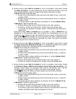
Figure 3 Component Layout for Murena board
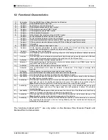
The following table shows the terminal functions for the Murena board
TERMINAL MS1
Term Symbol
Function
1
AL
Alarm Relay Contact (C)
2
AL
Alarm Relay Contact (NC)
3
TMP
Tamper Relay Contact (C)
4
TMP
Tamper Relay Contact (NC)
5
FLT
Fault Relay Contact (C)
6
FLT
Fault Relay Contact (NC)
7
STBY
Stand-by Command Input (Normally Open from GND)
8
TST
Test Command Input (Normally Open from GND)
9
GND
Ground Output
10
SYNC Synchronisation Output/Input, for Master/Slave
TERMINAL MS2
Term. Symbol
Function
1
13,8V
Positive Power Supply Input (+13,8 V
)
2
GND
Negative Power Supply Input and for Data (0 V
)
3
LH
+RS 485 Data Line High
4
LO
- RS 485 Data Line Low
Содержание Murena
Страница 38: ...NOTE...
Страница 39: ...NOTE...


