


Page 10
V+ is equal to the raw input voltage (i.e. 3.0...5.5V) when
Nano_Link
is asleep, and 5.0V when it is awake.
Nano_Link
records the current state of each digital input. In addition, it maintains an internal 16-bit counter for each
input, which is incremented each time the contact closes. Each input can therefore be used to monitor a digital state or
to count input pulses. The count is copied into non-volatile memory every 10 minutes, so in the event of a total power
failure in the worst case only 10 minutes of counts will be lost.
The counters can be reset to zero using a special test mode (see Chapter 0).
3.4.1.1 Pseudo Digital Input 1 – Comms Fail alarm
This is set to ‘1’ under normal conditions, but changes to ‘0’ in the event of loss of communications. It is described in
more detail in Sections 7.2 and 8.2.
3.4.1.2 Pseudo Digital Input 2 – Battery Low alarm
This is set to ‘1’ under normal conditions, but changes to ‘0’ when
Nano_Link
senses that the supply voltage is
dropping to the point where failure is imminent. It is described in more detail in Sections 7.2 and 8.2.
3.4.2 Digital Outputs
Digital outputs, if equipped, use volt-free relay contacts rated 125VAC/0.5A/60VA max. or 24VDC/1A/30W max.
The four outputs share a common return, but are fully isolated from the internal circuitry.
Note that the digital outputs copy the state of the corresponding remote digital inputs, combined with alarm flags as
described in 7.2 and 8.2.
Although the relay contacts are rated up to 125VAC, the user must exercise due caution to ensure that the safety
requirements of the Low Voltage Directive are not breached by the application of an unsafe voltage from an external
source.
If the relays are used to switch inductive loads, such as interposing relays, the load must include transient suppression
to prevent excessive voltages during switching. If the load is DC, this is most easily achieved by connecting a reverse-
biased diode across the load. If it is AC, a bi-directional suppressor such as transorb or a voltage dependent resistor
should be used
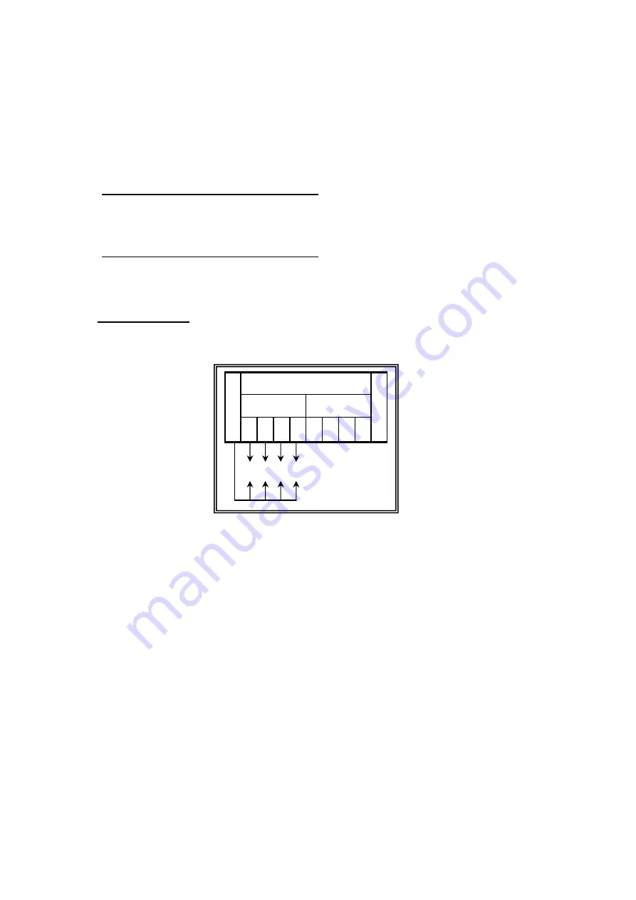
M
DIGITALS
M
CO OUTPUTS
INPUTS
CO
O/
P
1 2 3 4 1 2 3 4
I/P
Содержание Nano Link IP67
Страница 40: ...Page 38...