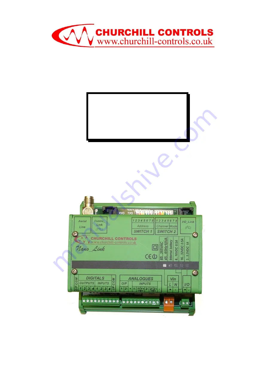
Nano_Link
TECHNICAL MANUAL
RADIO/LAND LINE TELEMETRY & TELECONTROL SYSTEM
WITH BATTERY-POWER OPTION
Страница 1: ...Nano_Link Nano_Link TECHNICAL MANUAL RADIO LAND LINE TELEMETRY TELECONTROL SYSTEM WITH BATTERY POWER OPTION...
Страница 2: ...made to ensure the accuracy of this document Churchill Controls Limited will not be held liable for any errors or omissions As part of our policy of continuous improvement we would welcome any sugges...
Страница 3: ...4 3 1 Real Inputs 11 3 4 3 1 1 Potentiometer Interface 13 3 4 3 1 2 Voltage Output Transducers 13 3 4 3 2 Pseudo Analogue Input 1 Supply Volts 14 3 4 3 3 Pseudo Analogue Input 2 Radio Received Signal...
Страница 4: ...S2 6 S2 8 000 27 8 1 1 2 Slow Scan S2 6 S2 8 010 27 8 1 2 Radio Commissioning S2 6 S2 8 001 27 8 1 3 Radio Path Test Set S2 6 S2 8 011 28 8 2 Base station Alarm Handling 29 9 SPECIAL FEATURES OF NANO...
Страница 5: ...s that wherever possible the features described will be present in all future software issues The software version fitted within Nano_Link can be found by removing the cover and examining the label on...
Страница 6: ...nclosure As shown in the illustration a leased line unit can also incorporate a surge protection unit All variants can also include any of the power supply options and a rotation sensor A label is att...
Страница 7: ...he regulated MPT1411 band of 457 5MHz to 458 5MHz and 463 0MHz to 464MHz at power levels up to 5W or the unregulated MPT1328 band of 173 20MHz to 173 35MHz at a power level of 10mW 2 2 2 Leased Line N...
Страница 8: ...communications fail alarm and battery low alarm conditions It also has 2 analogue inputs which can be used with low cost millivolt transducers or conventional current loop transmitters A pseudo analo...
Страница 9: ...Supply Nano_Link works from an input supply of 3 0 5 5VDC which may be derived from a variety of sources via an internal power supply unit The current consumption is less than 50 A when asleep increas...
Страница 10: ...s size has to be calculated along with that of the solar panel to ensure that the system continues operation throughout the year Factors influencing the size of the panel and battery include the elect...
Страница 11: ...located for digital I O and another for analogue I O The pin functions are marked on the top cover 3 4 1 Digital Inputs Nano_Link has 4 identical digital inputs with a common return intended for use w...
Страница 12: ...upply voltage is dropping to the point where failure is imminent It is described in more detail in Sections 7 2 and 8 2 3 4 2 Digital Outputs Digital outputs if equipped use volt free relay contacts r...
Страница 13: ...ower It is used to power the analogue input and output circuits and the radio transmitter It is also available for powering transducers if required If SENSE is within 1V of either 0V or 12V the input...
Страница 14: ...when needed It will thus activate the 12V supply only when it receives a command requesting an analogue reading The supply is then raised for a short period before sampling the analogue to give the tr...
Страница 15: ...ing that clips onto DIN rail adjacent to Nano_Link and incorporates Span and Offset adjustment Details of connections to this module and the method of calibrating it are given in Application Note AN00...
Страница 16: ...If the mains supply fails the unit continues operating from internal trickle charged Nickel Cadmium batteries but the voltage will drop to about 4 5V reading 3600 When the batteries are approaching t...
Страница 17: ...switch 2 8 closed Although the outputs are calibrated to give 0 20 00mA they can produce up to 20 40mA to indicate fault conditions 3 4 5 Expansion Capability Nano_Link includes an I O_bus port that...
Страница 18: ...age is less than 1 5V However the sense can be inverted if required by setting switch 8 of the DIPswitch ON This can be summarised as follows Logic State Input State Switch 8 OFF Switch 8 ON Volt free...
Страница 19: ...lly closes the contact for logic 1 state and opens it for logic 0 However the sense can be inverted if required by setting switch 8 of the DIPswitch ON This can be summarised as follows Output State L...
Страница 20: ...nting i e out of the page towards the reader in the illustration shown Yagis are similar to end fed dipoles but with reflectors which focus the signal in the direction in which they are pointing i e t...
Страница 21: ...tecting equipment against induced transients provided they are correctly installed The most important aspect is the provision of a good earth to which the transient can be diverted Figure 1 below grap...
Страница 22: ...iver test see 9 4 2 10111111 253 Radio transmitter test see 0 00111111 252 Hardware I O test see 9 4 4 nnnnn111 224 251 Base station interrogating outstation address nnnnn000 see Chapter 8 nnnnnnnn 1...
Страница 23: ...l modem the data rate should be set to 1200 baud If using an external modem the data rate should be set as required Switch 12345 Transmission Data Rate 0xxxx 1200 baud 1xxxx 300 baud 5 2 3 S2 6 S2 8 O...
Страница 24: ...ee contacts Energising voltage Supply voltage 3 0 5 5V when asleep 5 0V when awake Switching current 50mA wetting current 10 A continuous Maximum count rate 50 pulses second Outputs Optionally 4 digit...
Страница 25: ...t needs e g if it is not reading analogues it does not request them to minimise the time the transmitter is on If there is no power at the outstation site there will be no plant to control so the outs...
Страница 26: ...led the outstation will raise Note that while the outstation is in sniff mode i e when it has lost sync with the base station the transducer is not powered Its response to the first request will thus...
Страница 27: ...it knows that the sensor is rotating from south towards north Conversely if the new reading is less than the last it knows that the sensor is rotating from north towards south Therefore it knows that...
Страница 28: ...hes 3 out of every 4 1 Base station digital input 2 1 and Outstation battery mains supply is good Flashes continuously 4 flashes per second 2 0 Base station digital input 2 0 or Outstation battery mai...
Страница 29: ...econds This slows the system response but reduces the channel usage to less than 10 allowing the radio channel to be shared with other users in accordance with the requirements of de regulated radio H...
Страница 30: ...normally asleep to conserve battery power Every 10 seconds it interrogates the pushbuttons on the display module If any is pressed it wakes up and starts polling the outstation every 5 seconds The dis...
Страница 31: ...ttery mains supply is good and Base station battery mains supply is good Flashes continuously 4 flashes per second 2 0 Outstation digital input 2 0 or Outstation battery mains supply is low or Base st...
Страница 32: ...ated When a rotation sensor is used the mode must be set accordingly See 7 1 8 9 2 Shaft Encoder Interface 9 2 1 General An incremental shaft encoder can be typically used to measure water level to a...
Страница 33: ...in built zero reference The facility to set the zero is therefore built into the outstation as described below Digital and analogue outputs are not available on versions with a shaft encoder interface...
Страница 34: ...nalogues are to be sampled If the outstation is set to low power mode it will wake up each time a sample is due apply power to the analogues wait for them to stabilise then read them and compare them...
Страница 35: ...4 3 Address 253 S1 10111111 Test Communications Device This mode allows various aspects of the communications device to be tested The following description assumes the unit is fitted with a radio but...
Страница 36: ...ST LED in opposite sync to HEARTBEAT if analogue or RSSI maximum value has been recorded xxxxx011 Copy digital inputs to digital outputs and uncorrected analogue input 2 to analogue output 2 Copy unco...
Страница 37: ...and buttons simultaneously The configuration allows the module to be set to Continuous or Low Power mode with the backlight either on or off In continuous mode the display is permanently active and k...
Страница 38: ...cting a shaft encoder will reset its count to zero 10 2 3 Radio Path Test mode The display sequences through the following note that the display can be frozen on any given state by pressing the button...
Страница 39: ...ressing the button will accept the currently displayed value This channel will remain until either A new value is selected through the display OR Any pole of switch S1 or S2 is changed OR Power is rem...
Страница 40: ...Page 38...
Страница 41: ...n Address 20 Continuous transmission 27 Data Rate 21 Digital Input Module 16 Digital Inputs 9 Digital Output Module 17 Digital Outputs 10 Exception Reporting 32 Expansion Capability 15 Housing 4 Indic...
Страница 42: ...r save mode analogue averaging 25 Power save mode Rotation Sensor 25 Private Wire 5 Pseudo Analogue Input 1 Supply Volts 14 Radio 5 Radio Channel 20 Radio Commissioning 27 Radio Path Test Set 28 Radio...