background image

5

Mounting Instructions

Heater Location Instructions:

Arrange units so their discharge air streams:
A. Are subjected to minimum interference from col-

umns, machinery and partitions.

B. Wipe exposed walls without blowing directly at 

them.

C. Are directed away from room occupants in comfort 

heating.

D.  Are directed along the windward side when installed 

in a building exposed to a prevailing wind.

Locate thermostat on interior partition walls or posts 

away from cold drafts, internal heat sources and away 

from heater discharge air streams.
Small rooms can be heated by one unit heater. Where 

two walls are exposed, the heater should be mounted 

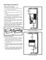
as shown in Figure A.
Large rooms require multi-unit installations. Number 

and capacity of units will be determined by volume of 

building and square feet of floor area to be heated. Ar-

range units to provide perimeter air circulation where 

each unit supports the air stream from another.

EXPOSED

EXPOSED

EXPOSED

EXPOSED

EXPOSE

D

EX

POS

ED

Figure A

Minimum Clearances

A. The heater must be mounted at least 7’ above the 

floor to avoid accidental contact with the heating 

elements or fan blade which could cause injury.

B.  Keep at least 5’ clearance in front of the heater. Re-

fer to figures 1 and 2 for side, top and back clear-

ance requirements.

C. The ceiling mounting structure and the anchoring 

provisions must be of sufficient strength to support 

the combined weight of the heater and mounting 

bracket.

D. The wall or mounting surface, and the anchoring 

provisions must be capable of supporting the com-

bined weight of the heater and the mounting brack-

ets cantilevered from the mounting surface.

Wall

Ceiling

Floor

Wall

Ceiling

10' (305 cm)

Min.

Floor

18"

(46 cm)

Min.

9" (23 cm)

Min.

12"

(30 cm)

Min.

7’ (214 cm)

Min.

Figure 1: Horizontal Mounting

Wall

Ceiling

Floor

Wall

Ceiling

10' (305 cm)

Min.

Floor

18"

(46 cm)

Min.

9" (23 cm)

Min.

12"

(30 cm)

Min.

7’ (214 cm)

Min.

Figure 2: Vertical Mounting

Содержание HD3D

Страница 1: ...1 Installation Operation and Maintenance Instructions HD3D Forced Air Heater Corrosion Resistant Hose Down PF200 8 161 305521 001 January 2015 ...

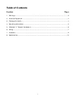
Страница 2: ...2 Table of Contents Section Page 1 Warnings 3 2 Optional Equipment 4 3 Package Contents 4 4 Mounting Instructions 5 5 Standard L Bracket Installation 6 6 Wiring 7 7 Operation 9 8 Maintenance 10 ...

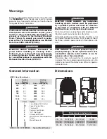
Страница 3: ...ury type thermostat directly on unit Vibration could cause heater to malfunction Fan blade rotation must be checked If airflow is not moving out through the louvers interchange any two of the three customer power leads on three phase units only FIRE HAZARD To prevent personal injury or property damage do not operate heater near combustible objects restrict aiflow or use for purposes other than des...

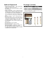
Страница 4: ... Factory installed heater on heater off fan only to permit air flow with or without energizing the heating elements The switch is ac cessible from outside the NEMA 4X enclosure On Pilot Light Factory installed to indicate when power is on Internal Fusing Factory installed Manual Reset Cutout Factory installed Disconnect Switch Field Factory installed See document PF928 for installation instruction...

Страница 5: ...ter air circulation where each unit supports the air stream from another EXPOSED E X P O S E D EXPOSED EXPOSED EXPOSED E X P O S E D Figure A Minimum Clearances A The heater must be mounted at least 7 above the floor to avoid accidental contact with the heating elements or fan blade which could cause injury B Keep at least 5 clearance in front of the heater Re fer to figures 1 and 2 for side top a...

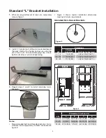
Страница 6: ...d rod sizes for in stallation to be supplied by installer are located in figure 3 Figure 4 shows typical installation dimensions meeting minimum requirements Standard Non Swivel Brackets A Typ 120 120 Figure 3 Dimensions kW A Radius Inches cm Bolt Size Inches mm 2 7 5 7 3 4 20 3 8 to 7 16 10 to 11 10 20 9 1 2 24 3 8 to 7 16 10 to 11 25 39 11 1 2 29 3 8 to 7 16 10 to 11 Wall Ceiling Floor Wall Ceil...

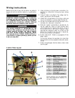
Страница 7: ...tch and may be controlled by a wall mounted thermostat 4 All units are provided with control and power termi nal blocks for customer s connection 5 Protection against overheating is provided by an internal automatic thermal cutout manual reset cutout optional which opens the electric circuit if the normal air flow is restricted or stopped Cutout automatically energizes heater on removal of the obs...

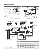
Страница 8: ...JUMPER WHEN THERMOSTAT IS USED OMIT FOR 1Ø IN HEATER CONTACTOR C2 C1 TIME DELAY CONTROL TERMINAL BLOCK SEC PRIMARY 40VA TRANSFORMER POWER CONTACTOR MOTOR X1 X2 H1 H2 RELAY 2 NC NOC 6 1 REFER TO NAMEPLATE FOR XFMR PRIMARY INPUT AND SECONDARY CONTROL VOLTAGE AR CUTOUT BUILT IN OR REMOTE THERMOSTAT FOR VOLTAGE AND PHASE SEE HEATER NAMEPLATE 1PH ELEMENT WIRING 3PH ELEMENT WIRING PINK BROWN BLK BRN YEL...

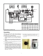
Страница 9: ...hru HD3DTSP 4000 Operation With proper installation this heater will provide efficient and dependable service Please read the following guidelines to ensure reliable operation 1 Do not allow objects such as fabric or other com bustible materials to restrict the airflow through the heater 2 Heater should not be operated unattended unless adequate controls and safety devices have been in stalled 3 T...

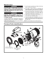
Страница 10: ...aters are provided with sealed ball bearings factory lubricated requiring no further lubrication under normal service conditions 3 Vacuum or hose off heater with water at city pres sure before activating for next heating season to remove accumulated dust or lint which otherwise may smoke or incinerate on initial heat up 4 Check internal and external wiring connections to ensure they have not becom...

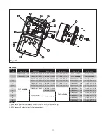
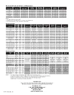
Страница 11: ...71 024 10 118 305471 101 118 305471 103 118 305471 104 118 305471 109 118 305471 105 12 5 118 305471 110 118 305471 112 118 305471 113 118 305471 117 118 305471 118 15 118 305471 201 118 305471 203 Not Available 118 305471 207 118 305471 208 20 Not Available 118 305471 209 118 305471 213 118 305471 214 25 Not Available 118 305471 304 118 305471 305 30 118 305471 309 118 305471 310 35 118 305471 31...

Страница 12: ...2 5 7 5 10 12 5 15 20 277 24 1 072 304551 002 072 123534 075 072 071847 043 315 304252 004 303 302177 010 168 053169 091 221 300463 002 5 7 5 10 12 5 15 20 480 24 1 or 3 072 304551 002 072 123534 075 072 071847 043 315 304252 002 303 302177 010 168 053169 092 221 300463 002 5 7 5 10 12 5 15 20 575 24 1 or 3 072 304551 002 072 123534 075 072 071847 043 315 304252 005 303 302177 010 168 053169 093 2...

Отзывы: