21
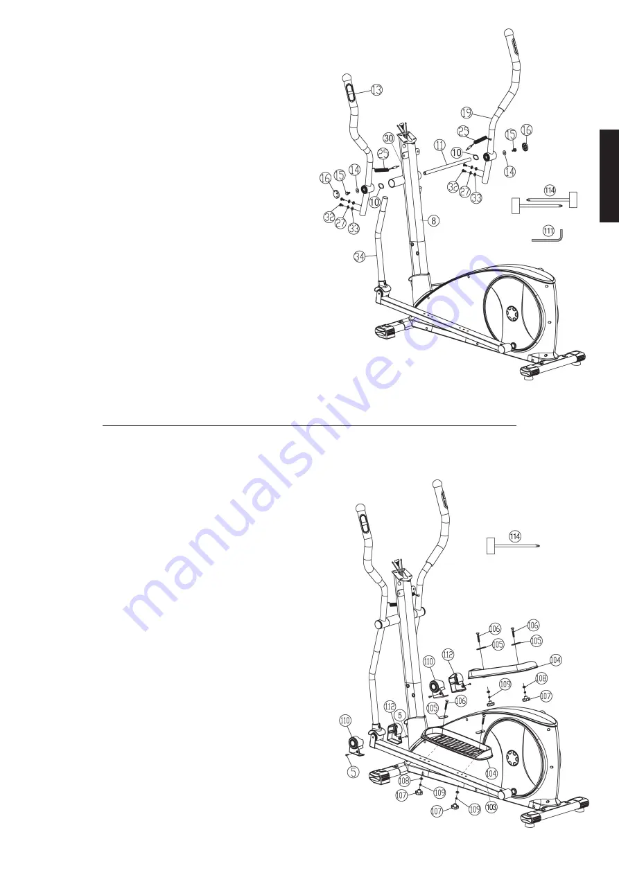
Step 4:
Installation of the handgrips (13+19) at connecting tubes (34) and
support (8).
1. Push the axle (11) into the middle position at handlebar support (8) and
put on left hand side one wave washer 17//25 (10) and the hand grip
left (13) onto the axles’ end (11). (Note: Right and left are specified as
viewed standing on the machine during training. The handgrip bars
must be positioned after assembly, so that the upper ends are curved
outwards (away from the support (8)). For assembly adjust the handgrips
downwards). Put on the screw M8x16 (15) a washer 8//22 (14) and tighten
it firmly.
2. Install the right handgrip (19) incl. all additionally required parts on the
right hand side of the machine as described in 1. To tighten the screws
(15) firmly use both tools (114) at the same time.
3. Push the connecting tubes (34) into the handgrips (13+19) and adjust
the holes in the tubes so that they are aligned. Put onto the bolts M8x16
(32) one spring washer (27) and curved washer 8//19 (33) and tighten
the handgrip bars (13+19) at connection tubes (34) firmly.
4. Put the pulse cables (25) at pulse connection (30) at front side of support
(8).
English
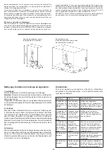
Step 5:
Installation of the footrests (104) at footrest holder (100+103).
1. Put the footrest (104) onto the left footrest holder (103). Adjust the
holes in the parts so that they are aligned. (Note: The high edges of the
footrests (104) must point inwards (towards the main frame. The position
adjusted in this way should always be equal at both sides. The positions
can change as desired at all times by removing the carriage bolts (106)
and sliding the footrests on the footrest brackets to get a more or less
flat movement.)
2. Push the carriage bolts M6x50 (106) from above with washer for pedal
(105) through the holes. The hole of washer for pedal (105) need position
more close to main frame. Put on a washer 6//13 (108) and a spring
washer for M6 (109) from the opposite side and tighten firmly with
handgrip nut (107).
3. Install the footrest (104) on right hand side on footrest holder (100) as
described in 1. – 2.
4. Install the connecting tube cover left and right (110+112) at intended
position in front of footrest holder left and right (100+103) and secure
with screws M5x12 (5).
Содержание 1827
Страница 4: ...4 ...


